

A tank adsorbent needs both suitable material and a path from the target species to its surface. NIST uses desiccants to separate water in a gravimetric gas-measurement system [1]; that method does not qualify an in-tank cartridge or its compatibility with an insulating mixture.
The placement review should include transport, capacity and the interfaces the cartridge changes. It must not assume that every adsorbent suits every insulating gas.
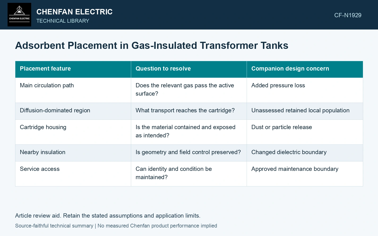
Map the access to the adsorbent
| Placement feature | Question to resolve | Companion design concern |
|---|---|---|
| Main circulation path | Does the relevant gas pass the active surface? | Added pressure loss |
| Diffusion-dominated region | What transport reaches the cartridge? | Unassessed retained local population |
| Cartridge housing | Is the material contained and exposed as intended? | Dust or particle release |
| Nearby insulation | Is geometry and field control preserved? | Changed dielectric boundary |
| Service access | Can identity and condition be maintained? | Approved maintenance boundary |
A convenient location is not automatically an effective one. A high-flow location can also be unsuitable if the housing creates another cooling or insulation problem.
Separate transport from capacity
Even a compatible adsorbent has a finite useful capacity under its qualified conditions. The relevant loading depends on the species, temperature and exposure history. A capacity figure from another gas or test condition cannot establish service performance.
Transport determines whether the target reaches the material; capacity determines what the material can retain under those conditions. A favorable result in one does not resolve the other.
Preserve the cartridge’s physical boundary
Containment needs evidence appropriate to the actual vibration, thermal and flow environment. Released particles can create concerns elsewhere in the tank. Check how the housing is supported and whether its location changes available electrical clearance.
Make condition evidence traceable
Record the installed material, batch or identity, location, service history and applicable assessment method. A later gas analysis can be influenced by the adsorbent’s presence or condition, so that record belongs beside the diagnostic interpretation.
If a cartridge is replaced or relocated, reassess its flow and dielectric interfaces. Identical nominal capacity does not establish equivalent placement or containment.
Assume water inventory 2 g and equilibrium capacity 0.10 g/g: minimum adsorbent is 20 g; 30 g provides nominal 3 g capacity. For placement, assume a well-mixed 1 m³ pocket exchanges q = 0.10 or 0.01 m³/h with a perfect downstream sink, without further moisture release. The author’s mass balance dC/dt = −qC/V [2] gives C/C0 = e⁻ᑫᵗ/ⱽ: after 10 h, 36.8% or 90.5% remains. Equal capacity therefore gives very different cleanup. Reject an isolated placement pending actual transport, isotherm, compatibility and containment qualification; these assumed rates are not drying-cycle instructions.
Increasing cartridge capacity will not correct a region that cannot exchange gas with it. Relocation is justified only when the target’s transport path improves without compromising containment, winding flow or electrical clearances. A later diagnostic trend must also be interpreted with the cartridge’s identity and loading history, because the adsorbent can alter the sampled population.
References
- NIST, Dew-point measurements for water in compressed gases, updated August 2025.
- U.S. Department of Energy, DOE-HDBK-1012/3-92, Thermodynamics, Heat Transfer, and Fluid Flow, Volume 3, 1992.