

A conductor, insulating support and frame need their own temperature histories. Wu et al. calculate and observe distinct temperatures in a particular gas transformer [1]; those temperatures are not a mechanical qualification of this support. NASA’s fastener manual explains how differential thermal movement can unload or overload a joint [2].
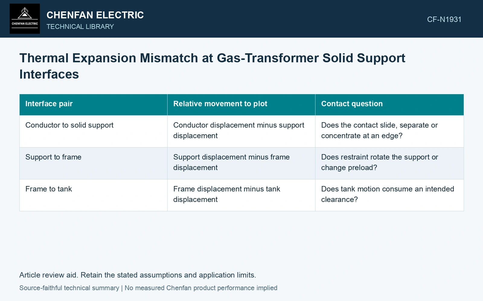
Put all three motions on the same drawing
For a freely expanding, uniform member, a first estimate is ΔL = α L ΔT. Here ΔL and original length L are in metres, α is the linear expansion coefficient in K⁻¹, and ΔT is the member’s temperature change in kelvin. Use each member’s own temperature change. Using the tank temperature for every component can erase the very mismatch being investigated.
For temperature-dependent α, integrate α(T) over the temperature range. A nonuniform component requires a spatial calculation as well. These free movements define displacement demand; they do not determine stress until the supports, clearances and stiffnesses are included.
| Interface pair | Relative movement to plot | Contact question |
|---|---|---|
| Conductor to solid support | Conductor displacement minus support displacement | Does the contact slide, separate or concentrate at an edge? |
| Support to frame | Support displacement minus frame displacement | Does restraint rotate the support or change preload? |
| Frame to tank | Frame displacement minus tank displacement | Does tank motion consume an intended clearance? |
Follow the return path through a temperature cycle
Plot relative displacement against temperature at the interface, with separate heating and cooling traces. A purely elastic model returns to its starting point. Frictional slip, creep, compression set or a loose joint may leave a different return position. The cold condition after a heat cycle can therefore be more informative than the hottest condition alone.
Preload also needs a sign convention. A displacement that compresses one contact can unload another along the same restraint chain. Record the initial preload, the force-displacement relation and the point at which contact is predicted to open. A single overall expansion number cannot identify that transition.
Connect the mechanical result to the insulation geometry
A new gas-filled microgap changes the local material boundary. An edge that carries more load can also deform insulation or alter an adjacent gas clearance. Evaluate the resulting geometry using the intended electric-field model, rather than assuming that a mechanically small movement is electrically negligible.
Assume two freely expanding 0.50 m members warm by 60 K, with linear expansion coefficients 12 × 10⁻⁶ and 30 × 10⁻⁶ K⁻¹. Their free expansions are 0.36 and 0.90 mm, a 0.54 mm mismatch. If an assumed interface movement allowance is 0.40 mm, the free mismatch exceeds it by 0.14 mm. Reconstruct the actual restraint and contact response before changing support dimensions; a restrained assembly may convert mismatch into stress rather than the full relative movement.
The review can stay focused: identify the hottest conductor position, the maximum unloaded contact position and the final cold position after cycling. For each, retain the support contact state and relevant insulation clearances. If the mechanical model predicts a change of contact regime, that change deserves explicit verification before an unchanged electrical geometry is accepted.
References
- Y. Wu et al., Research on Heat Dissipation Performance of Eco-friendly Gas insulated Transformer with i-C4F7N/CO2 as the Insulation Medium, Journal of Physics: Conference Series 2527, 012011, 2023. DOI: 10.1088/1742-6596/2527/1/012011.
- R. T. Barrett, Fastener Design Manual, NASA Reference Publication 1228, 1990.