

A multiport SST can regulate current, output voltage and link-energy states through its actual conversion stages [1]. Shared links and actuator limits couple these loops; assign each controlled state and actuator before choosing bandwidths.
The review should map the state each loop controls, the actuator it uses and the time range in which its assumptions are valid. A fixed rule that every outer loop be a certain number of times slower cannot establish stability for every architecture.
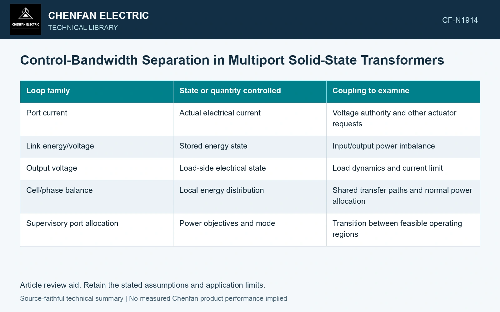
Assign physical ownership to the loops
| Loop family | State or quantity controlled | Coupling to examine |
|---|---|---|
| Port current | Actual electrical current | Voltage authority and other actuator requests |
| Link energy/voltage | Stored energy state | Input/output power imbalance |
| Output voltage | Load-side electrical state | Load dynamics and current limit |
| Cell/phase balance | Local energy distribution | Shared transfer paths and normal power allocation |
| Supervisory port allocation | Power objectives and mode | Transition between feasible operating regions |
The table identifies roles, not required loop frequencies. Actual topology determines which roles can be separated.
Test the intended hierarchy
A fast inner response can allow a slower loop to use an approximate plant. That approximation needs validation over the relevant states. If inner control reaches a current or voltage limit, the outer-loop model can change abruptly.
Measurement delay, filtering and communication can reduce the available margin. Include their actual time references; a control block drawn without delay is a different system from the installed implementation.
Review the shared energy boundary
Power commands at several ports act on finite stored energy. If each controller assumes another port will absorb its transient, incompatible requests can move the link voltage toward a limit. The allocation design should specify which loop establishes the energy balance and how competing demands are resolved.
Locate current, isolated-transfer, link-voltage and output loops on the actual power topology [1]. NREL’s PHIL work demonstrates why an end-to-end loop model includes interface and sensor dynamics [2]; its test setup is not a universal SST hierarchy or bandwidth prescription.
Use both local and event validation
Small-signal analysis can assess behavior around a defined operating point. Startup, fault response, port disconnection and saturation may require another model or test. A stable linearized point cannot certify the entire mode map.
Verify representative power and load steps, control mode changes and credible failed signals. Preserve which behavior comes from a validated plant model and which has been tested in hardware.
Assume outer crossover 20 Hz, supporting current-loop bandwidth 1 kHz and a pure 2 ms communication delay. Delay lag is 14.4°; retuning the outer loop to 100 Hz gives 72°. If each hypothetical delay-free design has 45° phase margin, residual screens are 30.6°/−27° at unchanged crossover. Hold the faster design pending the full coupled-loop assessment. The 50:1 original ratio alone cannot establish stability, and saturation or crossover movement invalidates this simple subtraction.
The resulting control map should make clear who controls each energy state and how loop authority changes at a limit. It lets reviewers understand whether the hierarchy remains valid as ports change duty. Merely assigning progressively lower bandwidth numbers to the boxes does not establish that the shared system is stable.
References
- D.-M. Predescu and Ș.-G. Roșu, Solid State Transformers: A Review—Part I: Stages of Conversion and Topologies, Technologies 13, 74, 2025. DOI: 10.3390/technologies13020074.
- J. Wang, B. Lundstrom, I. Mendoza and A. Pratt, Systematic Characterization of Power Hardware-in-the-Loop Evaluation Platform Stability, NREL/CP-5D00-73162, December 2019, sections II and III.