

An LV load draws more current on one phase while total active power remains below the SST rating. The output stage may still reach a phase-current limit, and internal links may see an unequal or oscillating power demand. Total kVA is an incomplete acceptance test.
Identify the output connection and neutral arrangement first. A three-wire converter and a converter with a qualified neutral path cannot be assumed to serve the same load population.
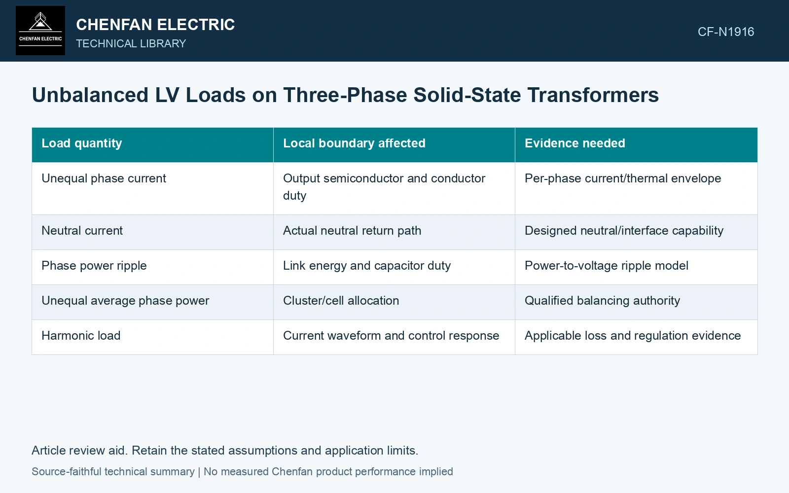
Follow each phase into the energy boundary
| Load quantity | Local boundary affected | Evidence needed |
|---|---|---|
| Unequal phase current | Output semiconductor and conductor duty | Per-phase current/thermal envelope |
| Neutral current | Actual neutral return path | Designed neutral/interface capability |
| Phase power ripple | Link energy and capacitor duty | Power-to-voltage ripple model |
| Unequal average phase power | Cluster/cell allocation | Qualified balancing authority |
| Harmonic load | Current waveform and control response | Applicable loss and regulation evidence |
A balanced input-current objective does not prove that every internal phase or cell remains balanced. The isolated stages and energy links determine how output demand is redistributed.
Use a single-phase illustration carefully
For sinusoidal voltage and current with RMS magnitudes V and I and displacement φ, instantaneous power contains VI cos φ plus a term oscillating at twice the electrical frequency. V is in volts and I in amperes, so both terms have units of watts.
Balanced three-phase contributions can cancel the corresponding ripple under ideal conditions. Unequal contributions need not cancel. The actual converter topology determines which link receives the remaining ripple. This illustration does not include arbitrary harmonics or switching effects.
Check local limits during regulation
A controller may maintain output voltage while shifting current or energy stress internally. Preserve per-phase and cell-level measurements or validated states. A satisfactory terminal voltage is not evidence that the hidden distribution is acceptable.
If the controller limits a phase, the resulting load voltage and protection behavior need assessment. Do not infer uninterrupted regulation beyond a hardware limit.
Define the unbalanced capability case
The SST conversion review distinguishes modular stages and their connections [1]. Reconstruct the actual phase, neutral and isolation-stage paths before applying the independent three-phase calculation [2]; a common total rating does not define each local current or energy limit.
Assume a four-wire 230 V RMS phase-to-neutral output with in-phase sinusoidal load currents 300/200/100 A and a 250 A per-phase limit. Total active power is 138 kW, below the balanced aggregate 172.5 kW, yet phase A uses 1.20 of its local limit. The 120° phase-current vector sum gives neutral current 173.21 A [2], not zero. Hold this load pattern unless the actual phase and neutral paths qualify; satisfactory aggregate power or terminal voltage cannot establish local capability.
The decision record should link that pattern to output current, link energy and thermal limits. It provides a clear basis for a specific uneven LV load. Applying a conventional-transformer derating factor or accepting total active power alone can miss the internal converter state that governs the service.
References
- D.-M. Predescu and Ș.-G. Roșu, Solid State Transformers: A Review—Part I: Stages of Conversion and Topologies, Technologies 13, 74, 2025. DOI: 10.3390/technologies13020074.
- U.S. Department of Energy, DOE-HDBK-1011/4-92, Electrical Science, Volume 4, 1992.