

An SST has a grid port and a proposed battery port. Their nominal powers do not automatically add to the LV output capability. The battery connection may put additional power through a shared isolation stage, or it may join a different link. The physical path decides the duty. [1]
Draw the battery connection at its actual node. Identify every stage crossed when charging, discharging or supporting another port. Do not place it on a convenient DC-link symbol without verifying that the interface is designed and qualified for that connection.
Keep power signs consistent
At one defined energy boundary, an illustrative balance is Pgrid + Pbatt = Pload + Ploss + dE/dt. Grid and battery powers are positive when entering that boundary; load power is positive when leaving. All are in watts, E is stored energy in joules and time is in seconds.
The equation does not identify the isolation-stage power until the boundary and connections are drawn. A battery on the LV side can create a different path from one on an upstream link.
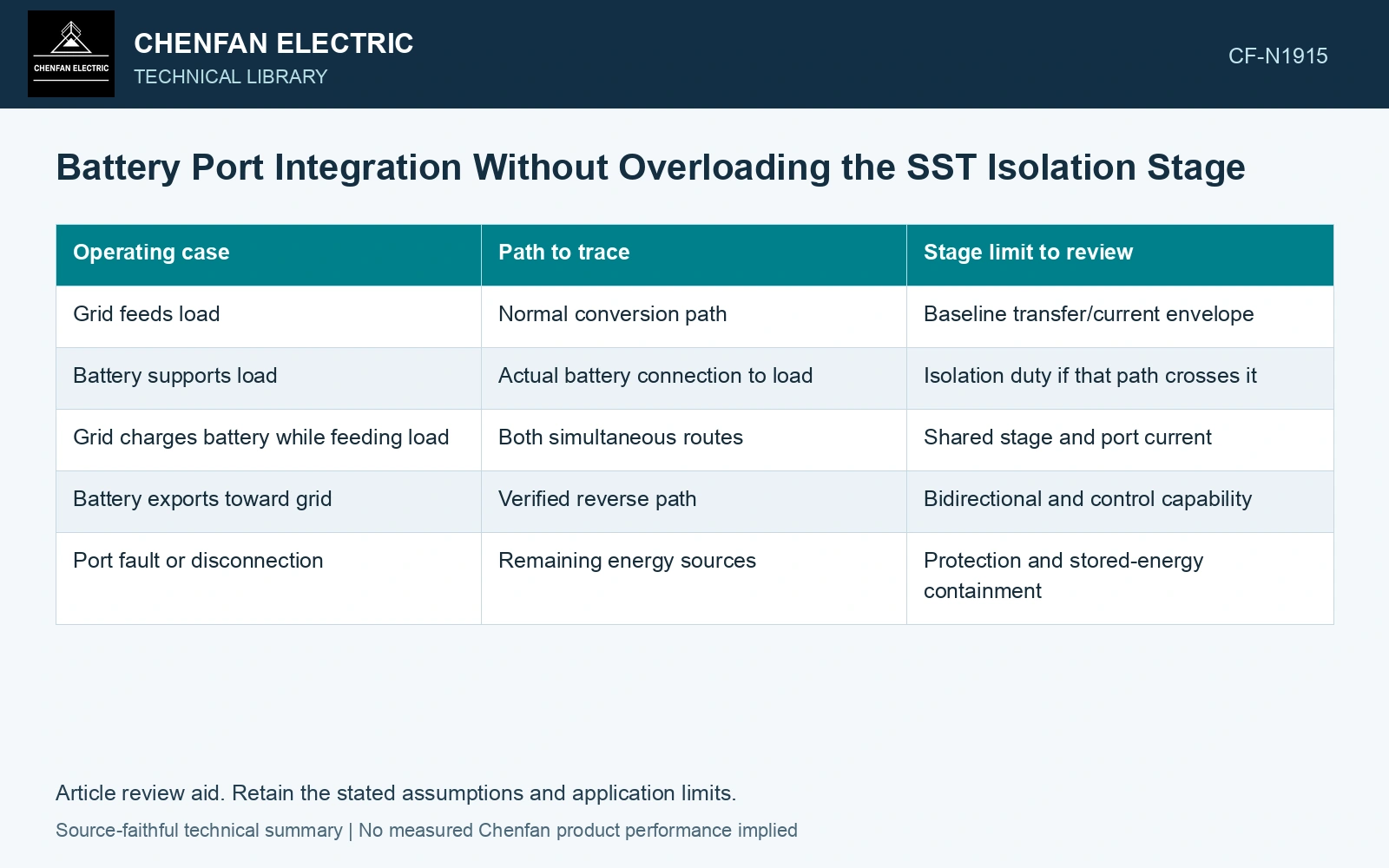
| Operating case | Path to trace | Stage limit to review |
|---|---|---|
| Grid feeds load | Normal conversion path | Baseline transfer/current envelope |
| Battery supports load | Actual battery connection to load | Isolation duty if that path crosses it |
| Grid charges battery while feeding load | Both simultaneous routes | Shared stage and port current |
| Battery exports toward grid | Verified reverse path | Bidirectional and control capability |
| Port fault or disconnection | Remaining energy sources | Protection and stored-energy containment |
Assess simultaneous duty
A stage may carry the algebraic net power in one arrangement and a larger combination of flows in another. Circulating or ripple current can create loss beyond what net active power suggests. Use the actual converter model and waveform rather than infer temperature from one watt value.
The battery’s voltage range also affects the interface. Equal power at another voltage can require different current and control authority. Keep this range in the operating map.
Qualify the new port as a service
A DC link in a research topology does not establish a customer-accessible battery port. Identify the designed isolation, sensing, current-control, protection and grounding interfaces, and trace which physical conversion stages carry the battery power. [2]
Compare limits before offering combined capacity
Request a simultaneous-port capability map with the assumed voltages, cooling, energy state and control mode. If one port’s demand reduces another’s available margin, show that relationship directly.
Assume both an 80 kW LV load and a 30 kW battery-charge request lie downstream of one isolation stage. Define its upstream input limit as 100 kW and assume transfer efficiency 95% at this state. Maximum downstream power is 95 kW, so the load leaves only 15 kW for charging. The requested 110 kW downstream requires 115.79 kW input, exceeding the defined limit by 15.79 kW. Reduce charging to at most 15 kW within this simplified envelope, then check actual currents, voltages, cooling and port limits. Do not compare input-rated and output-demand powers before accounting for losses.
The engineering result should identify the power crossing each shared stage and the conditions under which the ports can operate together. This gives the owner a usable multiport capability statement. Adding independent nameplate numbers can produce an output promise that no common isolation or converter stage was designed to carry.
References
- J. E. Huber and J. W. Kolar, Solid-State Transformers: On the Origins and Evolution of Key Concepts, IEEE Industrial Electronics Magazine 10(3), 2016. DOI: 10.1109/MIE.2016.2588878.
- D.-M. Predescu and Ș.-G. Roșu, Solid State Transformers: A Review—Part I: Stages of Conversion and Topologies, Technologies 13, 74, 2025. DOI: 10.3390/technologies13020074.