

A staged restart needs a process-readiness gate as well as an independently validated electrical permission. This article maps lubrication, cooling and recovery deadlines into that gate. It does not calculate the transformer’s voltage recovery or approve a motor-group schedule. [1]
Build the restart model from actual equipment relationships. A load’s commercial importance does not establish the order in which the process can safely recover.
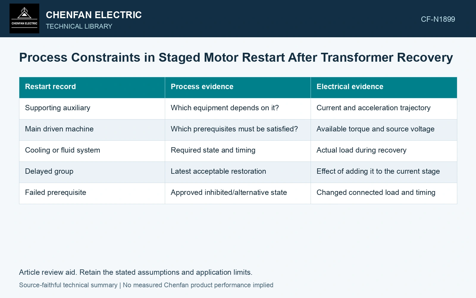
Record prerequisites and deadlines
For each restart candidate, identify required supporting systems, minimum conditions and the latest acceptable recovery time. The process owner must establish these inputs; they cannot be inferred from motor ratings.
| Restart record | Process evidence | Electrical evidence |
|---|---|---|
| Supporting auxiliary | Which equipment depends on it? | Current and acceleration trajectory |
| Main driven machine | Which prerequisites must be satisfied? | Available torque and source voltage |
| Cooling or fluid system | Required state and timing | Actual load during recovery |
| Delayed group | Latest acceptable restoration | Effect of adding it to the current stage |
| Failed prerequisite | Approved inhibited/alternative state | Changed connected load and timing |
Attach identities rather than labels such as high priority. A dependency graph should show which condition permits the next group, not merely where that group appears in a numbered list.
Assess each proposed stage dynamically
The transformer sees the sum of the connected loads at their current states. Motors from the previous stage may still be accelerating when the next begins. The model should retain their current trajectories rather than assume every earlier motor has reached normal load.
Check voltage, torque margin, current duration and protection behavior under credible source conditions. A lower peak can be accompanied by a longer elevated current period; assess the thermal consequence separately.
Include failed and late starts
A motor that fails to accelerate changes both the electrical burden and the process path. The approved logic needs to address that state rather than release the next stage on elapsed time alone. A status indicating commanded does not establish the supporting equipment is actually available.
The SEL paper evaluates a particular single-motor bus transfer [1]. Its electrical model is not a plant dependency schedule. Cummins addresses generator-set motor-starting behaviour [2]; use site-specific source and motor evidence before assigning any acceleration time here.
Starting and reacceleration require a source–motor model with changing real and reactive demand; nominal running kW cannot establish the recovery trajectory. [2]
Check the prerequisite window numerically
Assume achieved lubrication pressure is confirmed 4 s after supply recovery, a separately validated main-motor acceleration interval is 3 s, and the process deadline is 9 s. Earliest completion is 7 s, leaving 2 s of process-window slack. This arithmetic tests timing only. Late or missing pressure feedback keeps the process gate closed; even timely feedback cannot override an unavailable electrical permission.
References
- P. Muralimanohar, D. Haas, J. R. McClanahan, R. T. Jagaduri and S. Singletary, Implementation of a Microprocessor-Based Motor Bus Transfer Scheme, IEEE PCIC, 2016, DOI: 10.1109/PCICON.2016.7589248.
- G. Olson, Cummins, Specifying & Validating Motor Starting Capability, bulletin 5544188.