

A successful relay test with a steady nominal sine wave says little about a bus whose voltage and frequency are decaying while breakers and protection indications change state. Verification needs the signals that challenge the actual transfer algorithm. [1]
Recorded waveforms can anchor the test to observed behavior. Simulated traces can extend coverage, provided their origin and assumptions remain visible. Do not present a constructed extreme case as a field recording.
Preserve the waveform’s reference
Retain three-phase channels, time stamps, channel scaling and the alternate-source reference needed by the logic. Include the digital events that define breaker and protection states. A magnitude curve without phase information cannot fully exercise phase-aware transfer.
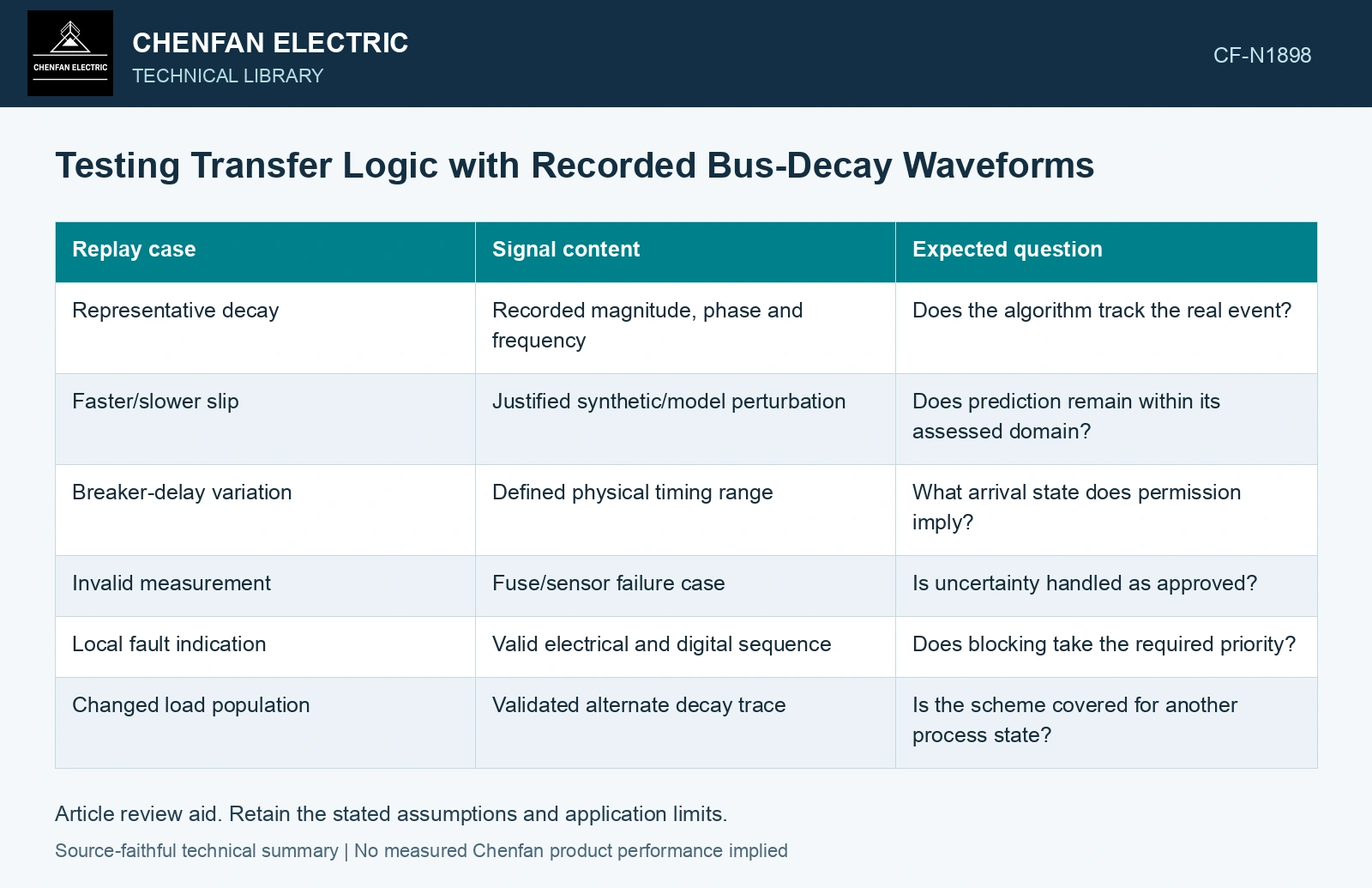
| Replay case | Signal content | Expected question |
|---|---|---|
| Representative decay | Recorded magnitude, phase and frequency | Does the algorithm track the real event? |
| Faster/slower slip | Justified synthetic/model perturbation | Does prediction remain within its assessed domain? |
| Breaker-delay variation | Defined physical timing range | What arrival state does permission imply? |
| Invalid measurement | Fuse/sensor failure case | Is uncertainty handled as approved? |
| Local fault indication | Valid electrical and digital sequence | Does blocking take the required priority? |
| Changed load population | Validated alternate decay trace | Is the scheme covered for another process state? |
Check the entire command-to-closure interval
Record when the relay permits transfer, when the command is issued and the modeled or measured closure. If the test substitutes an ideal fixed breaker delay, state that limit. Replay of the relay inputs does not physically verify a real mechanism’s timing.
The SEL implementation paper used simulated scenarios played back as COMTRADE files to assess tracking and transfer permission. It also discusses the value of comparison with actual rundown or transfer events. That distinction should remain in a new verification program.
Validate the perturbation before using it
Changing frequency without preserving continuous phase can create an artificial waveform discontinuity. Scaling voltage independently of a machine model can produce a physically inconsistent case. Such traces may still test an input boundary, but they should not be used as evidence of a real motor response without justification.
Keep boundary-testing traces separate from physically validated system cases. Both can be useful; they answer different questions.
Record the COMTRADE format/version with the channel scaling, time reference and digital-event map. The cited edition defines a waveform/event file format; conformance alone does not validate the physical trace or relay decision. [2]
Align replay and closure clocks
Assume a replayed close command occurs at 120 ms and the breaker delay spans 45–65 ms. Contact arrival spans 165–185 ms. Compare the expected permission with the waveform throughout that interval; a relay output checked only at 120 ms does not verify the arrival state. These are test assumptions, not breaker ratings.
References
- P. Muralimanohar, D. Haas, J. R. McClanahan, R. T. Jagaduri and S. Singletary, Implementation of a Microprocessor-Based Motor Bus Transfer Scheme, IEEE PCIC, 2016, DOI: 10.1109/PCICON.2016.7589248.
- IEEE/IEC, IEEE/IEC C37.111-2013, Measuring relays and protection equipment — Part 24: Common format for transient data exchange (COMTRADE) for power systems (historical edition).