

A synchronous motor on the bus can continue influencing voltage after the supply trips. Its contribution depends on excitation, rotor motion and the connected network. Substituting the decay curve of an induction motor discards precisely the states that make the machine different. [1]
A mixed-motor model should identify synchronous machines explicitly, including their field supply and control behavior during the interruption. Rated power and inertia alone are insufficient.
Preserve the excitation boundary
Determine whether the field system remains supplied, decays or trips. Include relevant excitation control and protection events. A sustained internal EMF and a common bus voltage are not identical quantities; the machine impedance and network determine their relationship.
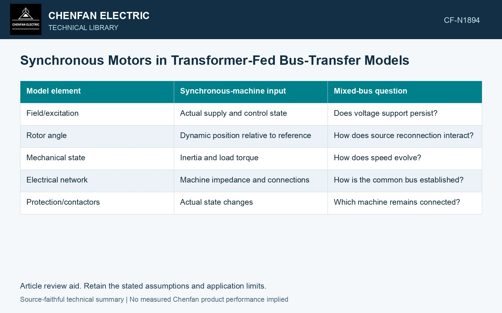
| Model element | Synchronous-machine input | Mixed-bus question |
|---|---|---|
| Field/excitation | Actual supply and control state | Does voltage support persist? |
| Rotor angle | Dynamic position relative to reference | How does source reconnection interact? |
| Mechanical state | Inertia and load torque | How does speed evolve? |
| Electrical network | Machine impedance and connections | How is the common bus established? |
| Protection/contactors | Actual state changes | Which machine remains connected? |
The induction machines on the same bus retain their own flux and speed dynamics. A common bus does not mean the internal machine states are identical.
Distinguish re-energization from resynchronization
Incoming source voltage acts on the synchronous machine’s existing angle and excitation state. Its electrical torque can change sharply. The shaft system then responds through its coupled mechanical dynamics. A voltage magnitude match cannot establish acceptable behavior throughout that response.
If the machine has separated from the bus, its later reconnection is a different case from a machine that remained connected. Preserve the actual topology and control permissions rather than assuming the same transfer model covers both.
Validate the mixed population
The SEL transfer paper notes that both synchronous and induction machines can sustain decaying terminal voltage, while its detailed example uses one induction motor. Its validated example cannot establish a synchronous-machine model by substitution.
Compare the mixed model with credible manufacturer behavior or event evidence for bus magnitude, phase/frequency trajectory and relevant current/torque. An energy-equivalent aggregate may help computation, but it needs to preserve the quantities that govern the transfer decision.
A synchronous motor’s DC-excited rotor interacts with the rotating stator field. Preserve the actual excitation supply and rotor-angle state when establishing its terminal-voltage contribution. [2]
Separate equal speed from equal excitation
Assume two synchronous-machine simulations have identical rotor speed and inertia, but one retains field voltage while the other loses it. They are distinct initial states for the network solution. Compare terminal voltage and electromagnetic torque from each model, then validate the excitation response before accepting one aggregate representation.
References
- P. Muralimanohar, D. Haas, J. R. McClanahan, R. T. Jagaduri and S. Singletary, Implementation of a Microprocessor-Based Motor Bus Transfer Scheme, IEEE PCIC, 2016, DOI: 10.1109/PCICON.2016.7589248.
- U.S. Department of Energy, DOE-HDBK-1011/4-92, Electrical Science, Volume 4, 1992.