

A drive-fed motor can keep rotating while its AC input loses voltage. Its electrical connection to the bus passes through a rectifier, DC link and inverter. That interface must be represented; the motor should not be inserted into the transfer model as another directly connected induction machine. [1]
For a conventional diode front end without another regenerative path, ideal input diodes do not provide controlled reverse power flow from the DC link to the AC bus. Real topology and protective components must be confirmed before using that assumption.
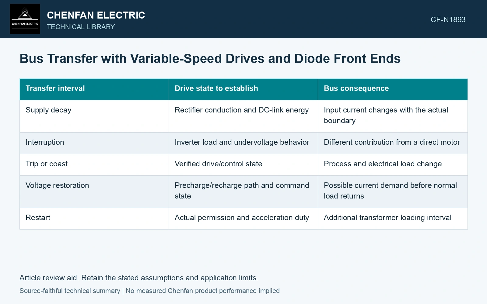
Track the DC-link state through the interruption
| Transfer interval | Drive state to establish | Bus consequence |
|---|---|---|
| Supply decay | Rectifier conduction and DC-link energy | Input current changes with the actual boundary |
| Interruption | Inverter load and undervoltage behavior | Different contribution from a direct motor |
| Trip or coast | Verified drive/control state | Process and electrical load change |
| Voltage restoration | Precharge/recharge path and command state | Possible current demand before normal load returns |
| Restart | Actual permission and acceleration duty | Additional transformer loading interval |
A drive can disconnect, continue briefly or follow another supported mode. The model should use its verified behavior, not a generic ride-through promise.
Use capacitor energy as a limited budget
For ideal capacitance C in farads, energy between DC voltages Vhi and Vlo is ΔE = 0.5C(Vhi² − Vlo²), in joules. Under an assumed constant net demand P in watts, an ideal energy-limited interval is ΔE/P in seconds.
This illustration excludes losses and assumes the stated voltage range is usable. It does not establish a drive’s actual undervoltage threshold, capacitor value or ride-through duration. Inverter control, motor regeneration and auxiliary supplies can alter the state.
Assess recharge separately from reacceleration
When AC voltage returns, the DC link may need charging before the drive resumes its process load. The actual precharge and protective design determines that input current. A capacitor-energy calculation alone cannot predict the recharge waveform.
Several drives restoring together can add a synchronized load on the transformer even if their motors restart later. Preserve both intervals rather than modeling only mechanical acceleration.
The capacitor exchanges stored electric-field energy with the connected circuit. Keep its usable voltage range and the actual rectifier/precharge path explicit when relating that energy to an interruption. [2]
Translate DC-link energy into time
Assume a 0.010 F DC link falls from 600 V to 450 V while supplying a constant net 20 kW. Available capacitor energy is 0.5 × 0.010 × (600² − 450²) = 787.5 J, giving 39.4 ms ideally. Losses and control limits shorten that budget; specify the actual drive response rather than treating rotor motion as AC-bus support.
References
- ABB, Technical guide No. 4: Guide to variable speed drives, 3AFE61389211, Revision C, May 2011.
- U.S. Department of Energy, DOE-HDBK-1011/3-92, Electrical Science, Volume 3, June 1992.