

The alternate source closes and the bus voltage returns. Several motors then draw substantial current while trying to recover speed. If that current depresses voltage enough, electrical torque can fall below load torque and the group can fail to accelerate. A favorable first-cycle voltage is not a complete stability result. [1]
The study must follow the coupled electrical and mechanical trajectory. Transformer impedance is part of the source seen by the motors; upstream source and cable impedance also belong in the model.
Track accelerating torque at each state
For a motor and load referred to one shaft, J dω/dt = Te − TL. J is inertia in kilogram-square metres, ω is speed in radians per second, and electrical torque Te and load torque TL are in newton-metres. Positive torque margin accelerates the shaft under this simplified rigid-shaft balance.
The electrical torque depends on voltage, speed/slip and machine state. In a limited fixed-slip induction-machine comparison, torque often varies approximately with voltage squared. That approximation is not a complete transient model and should not be extended across the whole recovery without validation.
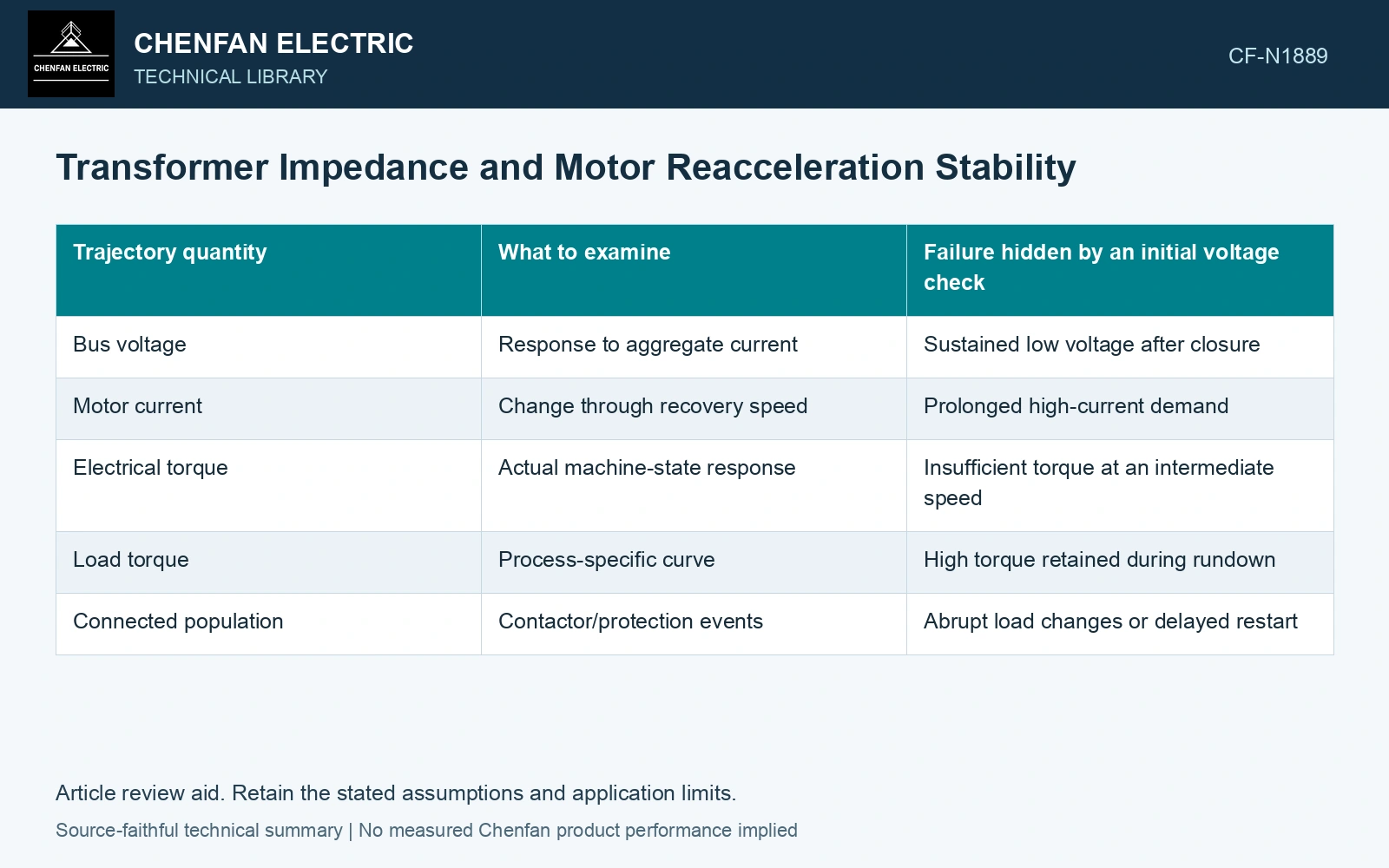
| Trajectory quantity | What to examine | Failure hidden by an initial voltage check |
|---|---|---|
| Bus voltage | Response to aggregate current | Sustained low voltage after closure |
| Motor current | Change through recovery speed | Prolonged high-current demand |
| Electrical torque | Actual machine-state response | Insufficient torque at an intermediate speed |
| Load torque | Process-specific curve | High torque retained during rundown |
| Connected population | Contactor/protection events | Abrupt load changes or delayed restart |
Expose the feedback loop
Reduced voltage can lower accelerating torque. Slower acceleration can retain high current for longer. That current sustains the voltage depression. The simulation should determine whether the system escapes this condition, stalls or is interrupted by protection.
Do not represent every motor with one locked-rotor current until rated speed. Current and torque curves, initial speed and machine magnetic state change the trajectory. A single-motor approximation also needs validation if the group contains materially different loads.
Compare the actual source alternatives
Different transformer paths can have different equivalent impedance and available voltage. Evaluate credible source states, not only the strongest one. A higher transformer rating does not by itself establish the lower total source impedance assumed by the model.
The SEL transfer paper uses a dynamic machine model and manufacturer torque/current data. Its method supports trajectory validation; its one refinery motor does not establish recovery of an unrelated motor group.
At a defined slip, reduced supply voltage can reduce induction-motor torque approximately with voltage squared; the load torque and inertia still determine acceleration. [2]
Keep acceleration margin in the reduced-voltage case
Assume available motor torque is 150 N·m at nominal voltage and scales locally with voltage squared at unchanged slip. At 0.8 pu voltage it becomes 96 N·m. Against an assumed 100 N·m load, the margin is −4 N·m, so that operating point cannot accelerate. Solve the coupled bus trajectory before crediting a stronger transformer path.
References
- P. Muralimanohar, D. Haas, J. R. McClanahan, R. T. Jagaduri and S. Singletary, Implementation of a Microprocessor-Based Motor Bus Transfer Scheme, IEEE PCIC, 2016, DOI: 10.1109/PCICON.2016.7589248.
- J. Rees, M. Kjellberg and S. Kling, ABB, Softstarter Handbook, 1SFC132060M0201, November 2010.