

A transfer study assumes every motor remains connected through the interruption. In service, some contactors release and others remain held by a separate control supply. The bus’s electrical population can therefore change before the alternate source closes. [1]
Modeling the AC bus voltage alone is insufficient. The contactor coil sees its actual control circuit, which may include a control transformer, stored energy, a DC supply or other interfaces.
Identify the control path for each group
Record coil type, supply origin and verified hold/release behavior under the applicable waveform. Use manufacturer and circuit evidence rather than a generic undervoltage number. Mechanical release and auxiliary indication also have timing boundaries that should be distinguished.
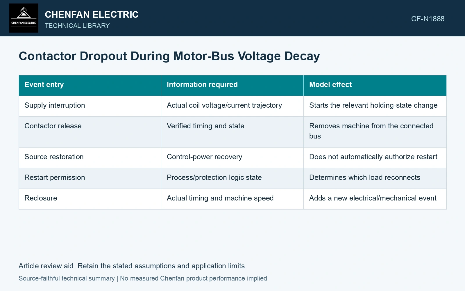
| Event entry | Information required | Model effect |
|---|---|---|
| Supply interruption | Actual coil voltage/current trajectory | Starts the relevant holding-state change |
| Contactor release | Verified timing and state | Removes machine from the connected bus |
| Source restoration | Control-power recovery | Does not automatically authorize restart |
| Restart permission | Process/protection logic state | Determines which load reconnects |
| Reclosure | Actual timing and machine speed | Adds a new electrical/mechanical event |
A contactor supplied from independent DC can remain closed while an AC-fed contactor releases. Conversely, a healthy bus can lose a load if its separate control supply fails. Preserve these cases rather than deriving every state directly from bus RMS voltage.
Update residual-voltage formation
A disconnected motor no longer contributes through the same bus path. Its rotor can continue turning, but its electrical state is now separated until reclosure. An aggregate model that retains its contribution can predict a different decay trajectory from the real system.
Track load steps at their actual event times. Changes in connected passive load can also influence the bus, so the model should not remove only the motor source while leaving its previous electrical demand unchanged.
Assess reclosure as another transient
After supply restoration, a motor may be coasting at a different speed and magnetic state. Its restart or reconnection needs the appropriate assessed duty. A restored contactor supply is not evidence that simultaneous automatic reclosure is acceptable for the transformer or process.
The SEL transfer paper models changing bus dynamics and validates transfer logic with waveforms. A site model should extend that discipline to its actual contactor states rather than assume that a successful relay algorithm guarantees the intended load remains connected.
Trace the starter’s power and control circuits separately. An external control supply can preserve a control command while the motor bus changes state; confirm the actual device and wiring before assigning a dropout event. [2]
Represent dropout as a topology event
Assume a contactor opens 80 ms into a recorded decay while its motor model remains connected until 200 ms. The model retains a nonexistent contribution for 120 ms. Correct the switching event before tuning the decay curve; a fitted voltage trace cannot justify the wrong connected-machine population. These times are illustrative assumptions.
References
- P. Muralimanohar, D. Haas, J. R. McClanahan, R. T. Jagaduri and S. Singletary, Implementation of a Microprocessor-Based Motor Bus Transfer Scheme, IEEE PCIC, 2016, DOI: 10.1109/PCICON.2016.7589248.
- J. Rees, M. Kjellberg and S. Kling, ABB, Softstarter Handbook, 1SFC132060M0201, November 2010.