

A motor bus has decayed to a lower voltage. Reconnecting it can still create a substantial electrical step if that residual voltage opposes the incoming source. The relevant phasor question includes both magnitude and angle. [1]
That question is useful but limited. Frequency, magnetic state and the motor’s electrical and mechanical dynamics determine the subsequent current and torque. A phasor difference does not replace the transient model.
Calculate the vector separation
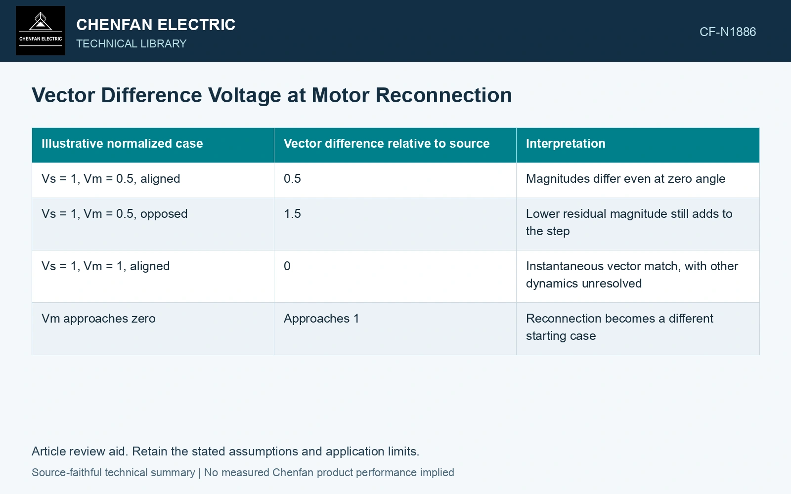
Let Vs and Vm be source and residual-bus voltage magnitudes in volts, referenced consistently, and let δ be their phase-angle difference. The magnitude of their vector difference is D = sqrt(Vs² + Vm² − 2VsVm cos δ), in volts. The expression compares sinusoidal voltage vectors at a defined instant and reference; it does not itself calculate current or torque.
| Assumed normalized RMS case | Vector difference relative to source | Interpretation |
|---|---|---|
| Vs = 1, Vm = 0.5, aligned | 0.5 | Magnitudes differ even at zero angle |
| Vs = 1, Vm = 0.5, opposed | 1.5 | Lower residual magnitude still adds to the step |
| Vs = 1, Vm = 1, aligned | 0 | Instantaneous vector match, with other dynamics unresolved |
| Vm approaches zero | Approaches 1 | Reconnection becomes a different starting case |
These are geometric illustrations, not permitted transfer conditions. The actual assessment must use consistent voltage units or bases and the predicted state at contact closure.
Keep frequency in the interpretation
A decaying motor bus can have a changing frequency. Matching an instantaneous angle does not imply that the magnetic states will remain aligned afterward. V/Hz quantities can be relevant in an appropriate assessment, but a voltage-only vector comparison should not be mislabeled as a complete flux criterion.
The SEL transfer paper explicitly cautions that simplified torque expressions can fail to represent real reconnection torque. Its dynamic approach supports retaining motor and shaft information beyond the voltage geometry.
Examine the machine and shaft response
Incoming voltage acts on a machine with existing flux and rotor position. The transient electrical torque then acts through the coupled shaft and load. Electrical air-gap torque and shaft stress are related but different quantities. A favorable vector difference cannot establish the maximum stress in every mechanical component.
Use the credible source impedance, machine states and breaker timing range in the dynamic case. Different fault histories can create different states even when the same residual magnitude is measured.
Use one phasor reference and a common RMS base before subtracting AC voltages. The geometric difference is an electrical input; converting it into current still requires the connected impedance and machine state. [2]
Use the equation as a screening artifact
The approval result should come from the complete assessed case. The equation contributes a transparent electrical comparison, with no universal safe threshold inferred. It is most valuable when it exposes the weakness of a magnitude-only claim before that claim reaches a transfer setting.
References
- P. Muralimanohar, D. Haas, J. R. McClanahan, R. T. Jagaduri and S. Singletary, Implementation of a Microprocessor-Based Motor Bus Transfer Scheme, IEEE PCIC, 2016, DOI: 10.1109/PCICON.2016.7589248.
- U.S. Department of Energy, DOE-HDBK-1011/3-92, Electrical Science, Volume 3, June 1992.