

Two sources reach the transfer bus at the same nominal voltage. Their phases can still differ because the paths include different transformer connections, phase permutations or measurement wiring. A voltage-magnitude comparison cannot detect those differences. [1]
Build a phase ledger from each source to the actual transfer point. Give every entry an explicit terminal reference and sign convention before adding it to the total.
Keep the electrical and measurement paths separate
The electrical path contains the transformers and conductor phase identities carrying power. The measurement path contains VTs or sensors and their secondary wiring. The relay compares the second path to infer the first. An unrecorded measurement offset can therefore make a correct physical comparison look incorrect, or conceal a real mismatch.
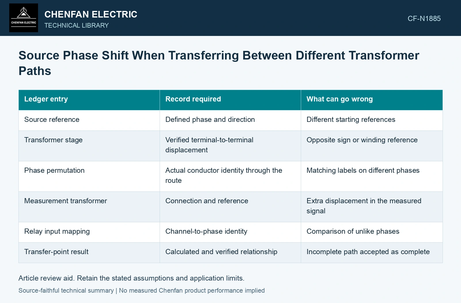
| Ledger entry | Record required | What can go wrong |
|---|---|---|
| Source reference | Defined phase and direction | Different starting references |
| Transformer stage | Verified terminal-to-terminal displacement | Opposite sign or winding reference |
| Phase permutation | Actual conductor identity through the route | Matching labels on different phases |
| Measurement transformer | Connection and reference | Extra displacement in the measured signal |
| Relay input mapping | Channel-to-phase identity | Comparison of unlike phases |
| Transfer-point result | Calculated and verified relationship | Incomplete path accepted as complete |
Add only compatible phase entries
Under a balanced sinusoidal reference, signed displacement angles can be accumulated along a defined path modulo a full cycle. This assumes the phase identity and voltage references are consistent. A phase permutation cannot always be handled by casually adding one angle to an otherwise unchanged label.
Compare both paths at their common transfer boundary. If they begin at different source references, include the source relationship as another input. The path ledger alone cannot establish synchronism between independent sources whose phase evolves with time.
Verify against terminal evidence
Trace the primary and secondary winding connections and the actual phase identities through each transformer path. Keep the power-terminal relationship distinct from the VT and relay-channel mapping used to observe it. [2]
Reconcile the signed path ledger
Assume one verified electrical path contributes +30° and its measurement mapping contributes −30°, while the second path contributes 0° on both entries. The relay inputs appear aligned although the physical paths differ by 30°. Resolve that mapping before a synchronism comparison; these assumed offsets illustrate why signal alignment and power-terminal alignment are different checks.
References
- P. Muralimanohar, D. Haas, J. R. McClanahan, R. T. Jagaduri and S. Singletary, Implementation of a Microprocessor-Based Motor Bus Transfer Scheme, IEEE PCIC, 2016, DOI: 10.1109/PCICON.2016.7589248.
- U.S. Department of Energy, DOE-HDBK-1011/4-92, Electrical Science, Volume 4, 1992.