

A neutral cable may carry little voltage to ground during normal balanced operation. That observation does not establish its insulation requirement. During an earth fault, the neutral can move in potential, and the cable, its ends and nearby grounded structures must support the assessed duty. [1]
Draw the voltage boundary from the transformer neutral terminal to the NGR connection. Include cable conductor, sheath or screen, termination, support and cabinet entry. The relevant question is potential difference across each insulating interface.
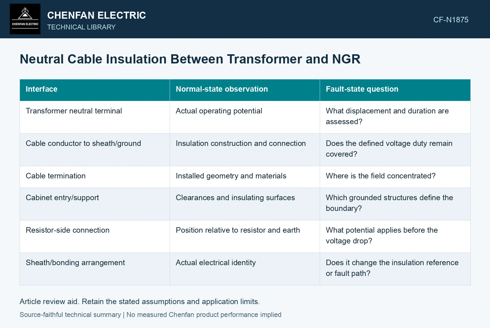
Keep normal and fault states separate
| Interface | Normal-state observation | Fault-state question |
|---|---|---|
| Transformer neutral terminal | Actual operating potential | What displacement and duration are assessed? |
| Cable conductor to sheath/ground | Insulation construction and connection | Does the defined voltage duty remain covered? |
| Cable termination | Installed geometry and materials | Where is the field concentrated? |
| Cabinet entry/support | Clearances and insulating surfaces | Which grounded structures define the boundary? |
| Resistor-side connection | Position relative to resistor and earth | What potential applies before the voltage drop? |
| Sheath/bonding arrangement | Actual electrical identity | Does it change the insulation reference or fault path? |
A current-flow diagram alone cannot answer these questions. Add the potential reference and the location of the resistor’s voltage drop. A cable connected on the neutral side of the resistor is not automatically near ground potential during a fault.
Use the actual grounding circuit
The voltage depends on the system connection, grounding impedance and fault. A direct neutral-resistor arrangement differs from one coupled through another transformer. Do not assign the system line voltage or a generic fraction of it to every interface without the circuit basis.
Power-frequency duration and transient stress are separate parts of insulation coordination. A cable or accessory voltage designation must be interpreted under its documented conditions. Similar outside dimensions do not establish equivalent field control or surface performance at the termination.
Follow the route through grounded metal
A neutral cable can pass close to tank steel, brackets and cabinet edges. Supports and bends determine that local geometry. Replacement during repair can change it even when the cable type is unchanged. Review the end interfaces rather than relying solely on the long cable section’s insulation data.
Contamination or condensation at the cabinet entry adds a surface boundary that is not represented by a dry bulk cable insulation rating. Keep the installed environmental condition in the assessment.
A displaced system neutral changes the earth-referenced voltage triangle. [2] Derive the neutral cable’s potential from that grounding state and its position relative to the resistor, then retain the termination’s actual duration and transient duties.
Calculate voltage at the neutral-side cable
For an assumed 6.6 kV line-to-line system with full neutral displacement in the simplified grounding model, neutral-to-earth voltage is 6,600/√3 = 3,810.5 V RMS. A neutral-side cable cannot be selected from its normally near-zero voltage. Check its specified power-frequency duration and transient duty using the actual connection.
References
- IEEE, IEEE C57.32-2015, IEEE Standard for Requirements, Terminology, and Test Procedures for Neutral Grounding Devices (historical edition).
- D. De Ronde, R. VanHatten and A. Wade, Loss of Effective System Grounding — Best Practices, Protection Challenges, and Solutions, Schweitzer Engineering Laboratories, 2015.