

A grounding transformer may also supply auxiliary power. That continuous service raises its thermal state before an earth fault occurs. The fault then adds a different current component through the grounding circuit. Reviewing the two ratings independently can miss their shared winding and insulation duty. [1]
The required evidence is a combined operating case. It should identify auxiliary load, grounding configuration, fault current, clearing time and the temperatures carried into the fault.
Map the shared components
Use the actual winding connection to identify which conductors carry normal load, fault-related zero-sequence current or both. Some thermal paths are shared even where electrical currents occupy different winding sections. Keep those distinctions in the design model.
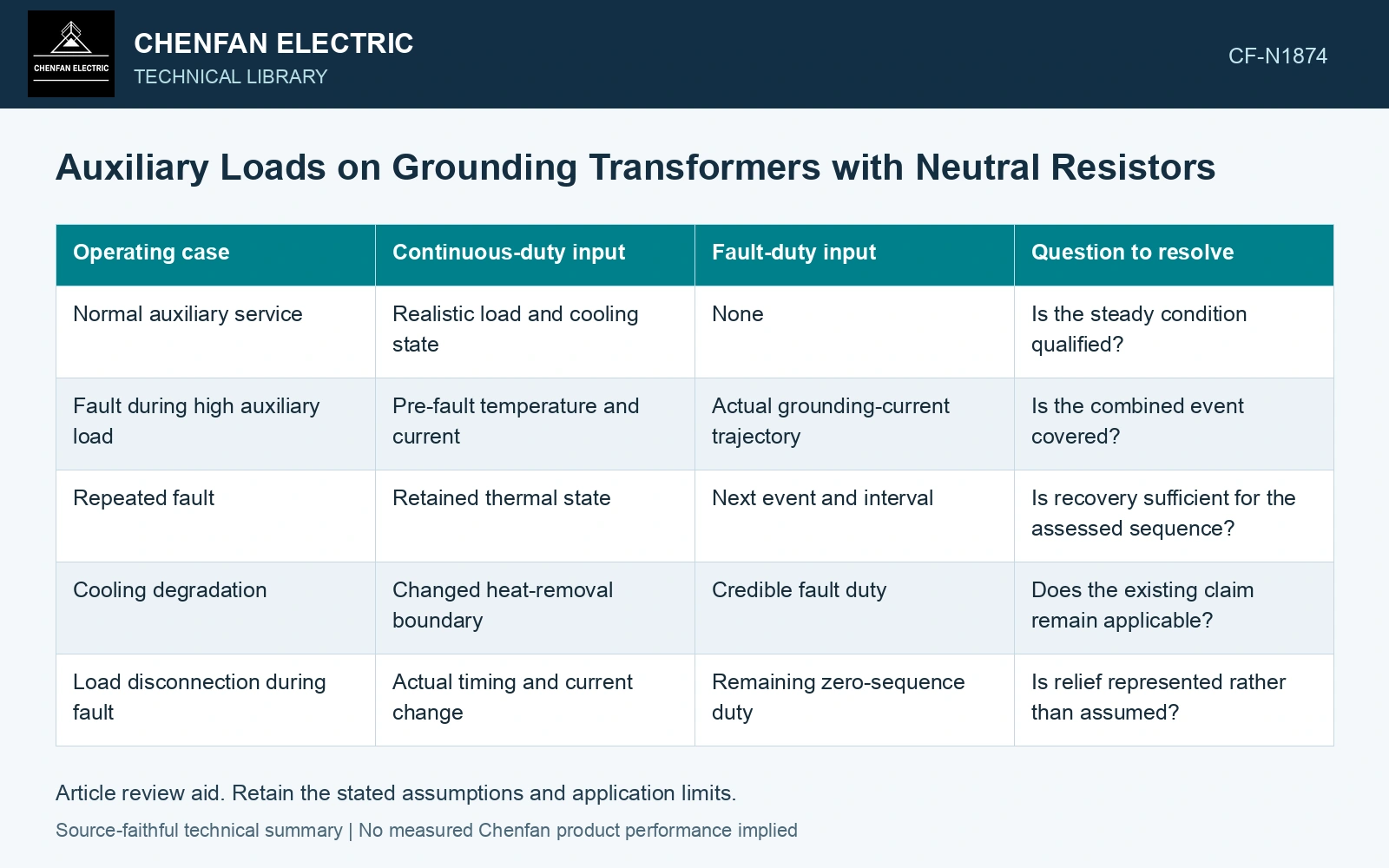
| Operating case | Continuous-duty input | Fault-duty input | Question to resolve |
|---|---|---|---|
| Normal auxiliary service | Realistic load and cooling state | None | Is the steady condition qualified? |
| Fault during high auxiliary load | Pre-fault temperature and current | Actual grounding-current trajectory | Is the combined event covered? |
| Repeated fault | Retained thermal state | Next event and interval | Is recovery sufficient for the assessed sequence? |
| Cooling degradation | Changed heat-removal boundary | Credible fault duty | Does the existing claim remain applicable? |
| Load disconnection during fault | Actual timing and current change | Remaining zero-sequence duty | Is relief represented rather than assumed? |
Add currents before calculating heat
Where current components share a conductor, instantaneous current is their algebraic sum. Loss depends on the square of that sum, not on simply adding two nameplate kVA values. The average cross-term may vanish in a justified symmetrical case, but it should not be discarded without checking the actual waveform and components. Cancellation in a symmetrical three-phase aggregate does not automatically remove the cross-term in each individual conductor.
Temperature-dependent resistance and local loss distribution also matter. A bulk thermal estimate cannot automatically identify the hottest region created by a new combined current pattern.
Read each rating on its own basis
A short-time grounding rating identifies a specified event. A continuous auxiliary rating identifies sustainable service under stated conditions. Neither is a spare capacity pool that can be transferred to the other by an arithmetic conversion.
The NGR itself has no obligation to carry the auxiliary load current unless the actual circuit places that current through it. Keep the resistor branch and transformer load branch separate in the schematic, then identify their thermal or electrical interactions.
Grounded-wye/delta and zigzag constructions provide different zero-sequence winding paths. Identify the actual closed-delta or cross-phase coil connections before mapping auxiliary and fault current into a conductor. [2]
Retain the conductor cross-term
Assumptions: one shared conductor carries 10 A and 6 A sinusoidal RMS components at 50 Hz with 60° phase displacement; take constant resistance 0.5 Ω. Its loss is 0.5(10² + 6² + 2×10×6×cos60°) = 98 W, versus 68 W from merely adding squared components. For an assumed 10 s fault, 100 J/K effective local heat capacity and 110 °C pre-fault temperature with cooling neglected, these give 119.8 °C and 116.8 °C respectively. Against an assumed 119 °C gate, omitting the cross-term would incorrectly pass this node. Reassess the shared conductor and the combined hot-start duty; neutral-resistor branch current remains a separate input.
References
- IEC, IEC 60076-6:2007, Power transformers — Part 6: Reactors.
- D. De Ronde, R. VanHatten and A. Wade, Loss of Effective System Grounding — Best Practices, Protection Challenges, and Solutions, Schweitzer Engineering Laboratories, 2015.