

A trench specification that names a thermal backfill product has only begun the engineering task. The cable needs a heat-transfer path with known dimensions and credible properties after installation. A product can meet a laboratory value while the trench contains voids, a thinner envelope or a different moisture condition. [1]
Specify the required thermal performance and how it will be verified in the installed arrangement. The purchasing description and the construction record should refer to the same design assumptions.
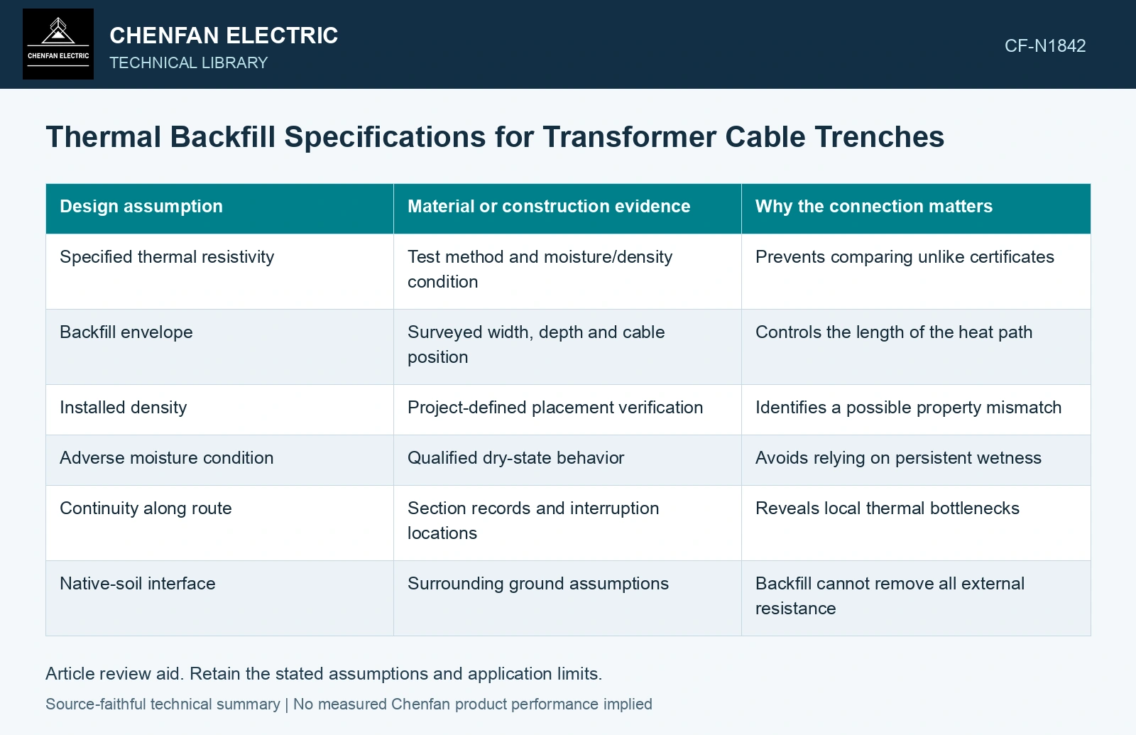
Tie each property to a physical condition
Thermal resistivity is not useful without the condition under which it was determined. Density, moisture and specimen preparation affect the meaning of a test. If the rating depends on dry-condition performance, a wet specimen result cannot silently replace it.
| Design assumption | Material or construction evidence | Why the connection matters |
|---|---|---|
| Specified thermal resistivity | Test method and moisture/density condition | Prevents comparing unlike certificates |
| Backfill envelope | Surveyed width, depth and cable position | Controls the length of the heat path |
| Installed density | Project-defined placement verification | Identifies a possible property mismatch |
| Adverse moisture condition | Qualified dry-state behavior | Avoids relying on persistent wetness |
| Continuity along route | Section records and interruption locations | Reveals local thermal bottlenecks |
| Native-soil interface | Surrounding ground assumptions | Backfill cannot remove all external resistance |
Treat geometry as part of the specification
The same material around different cable formations produces different thermal behavior. The design should show cable spacing, the required envelope and neighboring heat sources. Construction changes that move a cable toward the envelope edge alter the model even if every delivery ticket names the correct material.
Local interruptions deserve route identities. A crossing, joint bay or drainage feature can replace part of the planned thermal region. Assess its effect as a physical change rather than averaging it away across the whole route.
Avoid accepting paperwork in place of installation
Delivery certificates can establish batch identity and tested properties. They do not establish how the material was placed. Retain inspection evidence before the trench is closed, with identifiable sections and dimensions. Where an installed condition cannot be observed directly, use the project’s qualified verification method and record its limitations.
Unexpected material or placement should trigger a thermal reassessment using the actual condition. A small geometric change may or may not matter; only the model and credible inputs can establish its significance.
The series thermal resistances of internal cable layers and external trench material both enter the temperature rise. Test the installed backfill state in that same path before retaining the specified current rating. [2]
Check the delivered backfill condition
Assumptions: heat generation is 20 W/m, cable internal thermal resistance is 1.5 K·m/W, surrounding temperature is 30 °C and the conductor gate is 90 °C. External thermal resistance is 1.2 K·m/W in the design condition but 1.8 K·m/W in the delivered installed condition. Predicted conductor temperatures are 30 + 20(1.5 + 1.2) = 84 °C and 30 + 20(1.5 + 1.8) = 96 °C. The first passes with 6 K margin; the actual condition fails by 6 K. Its maximum loss under this fixed-property model is (90 − 30)/(1.5 + 1.8) = 18.18 W/m. Hold the declared rating and remediate or reassess the installed material/envelope rather than accepting the product label. [1][2]
References
- IEC, IEC 60287-1-1:2023, Electric cables — Calculation of the current rating — Part 1-1: Current rating equations (100 % load factor) and calculation of losses — General.
- U.S. Department of Energy, DOE-HDBK-1012/2-92, Thermodynamics, Heat Transfer, and Fluid Flow, Volume 2, 1992.