

Most of a feeder route may have generous thermal margin while a short crossing approaches the conductor limit. A hot pipe or another loaded cable creates a local boundary condition that a uniform route calculation can miss. The crossing’s short length does not make its peak temperature harmless. [1]
Describe the intersection in three dimensions. Its angle, separation, depth and surrounding materials determine how heat paths overlap. A parallel-circuit correction factor cannot be assumed to represent a perpendicular crossing.
Keep the two heat sources independent
The transformer feeder generates conductor, dielectric and metallic-layer losses according to its cable design and duty. The other source has its own temperature or heat output and operating history. Specify which quantity is known. A pipe temperature and an imposed heat flux are different boundary conditions.
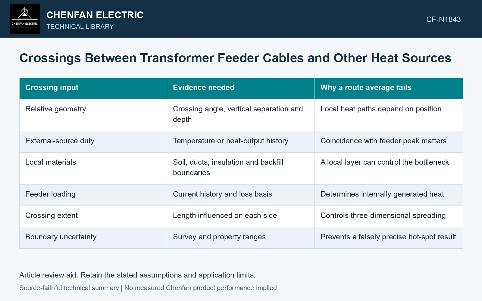
| Crossing input | Evidence needed | Why a route average fails |
|---|---|---|
| Relative geometry | Crossing angle, vertical separation and depth | Local heat paths depend on position |
| External-source duty | Temperature or heat-output history | Coincidence with feeder peak matters |
| Local materials | Soil, ducts, insulation and backfill boundaries | A local layer can control the bottleneck |
| Feeder loading | Current history and loss basis | Determines internally generated heat |
| Crossing extent | Length influenced on each side | Controls three-dimensional spreading |
| Boundary uncertainty | Survey and property ranges | Prevents a falsely precise hot-spot result |
Choose a model that represents the intersection
For linear, constant-property heat conduction, contributions from separate heat sources can be superposed. That principle helps organize a calculation: the conductor rise caused by its own losses and the rise caused by the crossing source are distinct terms. It does not justify adding two unrelated derating percentages.
If thermal properties vary with temperature or moisture, the simple linear assumption may fail. The model must also represent axial heat spreading where it matters. A long parallel section and a compact crossing can have different peak-temperature shapes even with the same closest separation.
Test the credible coincidence
A hot pipe operating mainly outside the feeder peak creates a different problem from one at maximum output during the hottest load period. Use justified coincident scenarios rather than independently selecting convenient average conditions. Where duty is uncertain, retain a range and identify the scenario that governs.
Linear heat conduction permits superposition only for consistent geometry and boundary conditions with constant properties. Keep the crossing-source contribution separate when solving the feeder’s permissible own-loss term. [2]
Keep the crossing contribution local
Assumptions: at 400 A, cable self-heating produces 45 K rise, a coincident hot-pipe crossing adds 12 K, ambient is 35 °C and the conductor gate is 90 °C. Away from the crossing, temperature is 80 °C; locally it is 35 + 45 + 12 = 92 °C and fails by 2 K. If the pipe contribution stays 12 K and cable loss scales with I² at fixed resistance, only 90 − 35 − 12 = 43 K remains for self-heating. The local current bound is 400√(43/45) = 391.01 A. Hold 400 A operation in that coincidence; revise the route, thermal barrier or load using the full three-dimensional crossing model. [1][2]
References
- IEC, IEC 60287-1-1:2023, Electric cables — Calculation of the current rating — Part 1-1: Current rating equations (100 % load factor) and calculation of losses — General.
- U.S. Department of Energy, DOE-HDBK-1012/2-92, Thermodynamics, Heat Transfer, and Fluid Flow, Volume 2, 1992.