

A cooler guarantee can specify a clean bundle or an added fouling resistance. Put these on the same area basis before comparing thermal duty. DOE’s heat-transfer treatment relates total resistance, overall coefficient and the mean temperature difference [1]; the clean factory result does not measure future deposits.
Express all resistances on a common area basis before adding them. In a simplified overall coefficient, 1/U = 1/hoil + Rf,oil + Rwall + Rf,water + 1/hwater. U and h are W/(m²K); resistance terms are m²K/W. Rwall represents the complete separating-wall assembly; a double-wall construction also needs its inter-wall contact or gap resistance included. Cylindrical tubes require area conversion between their inner and outer surfaces.
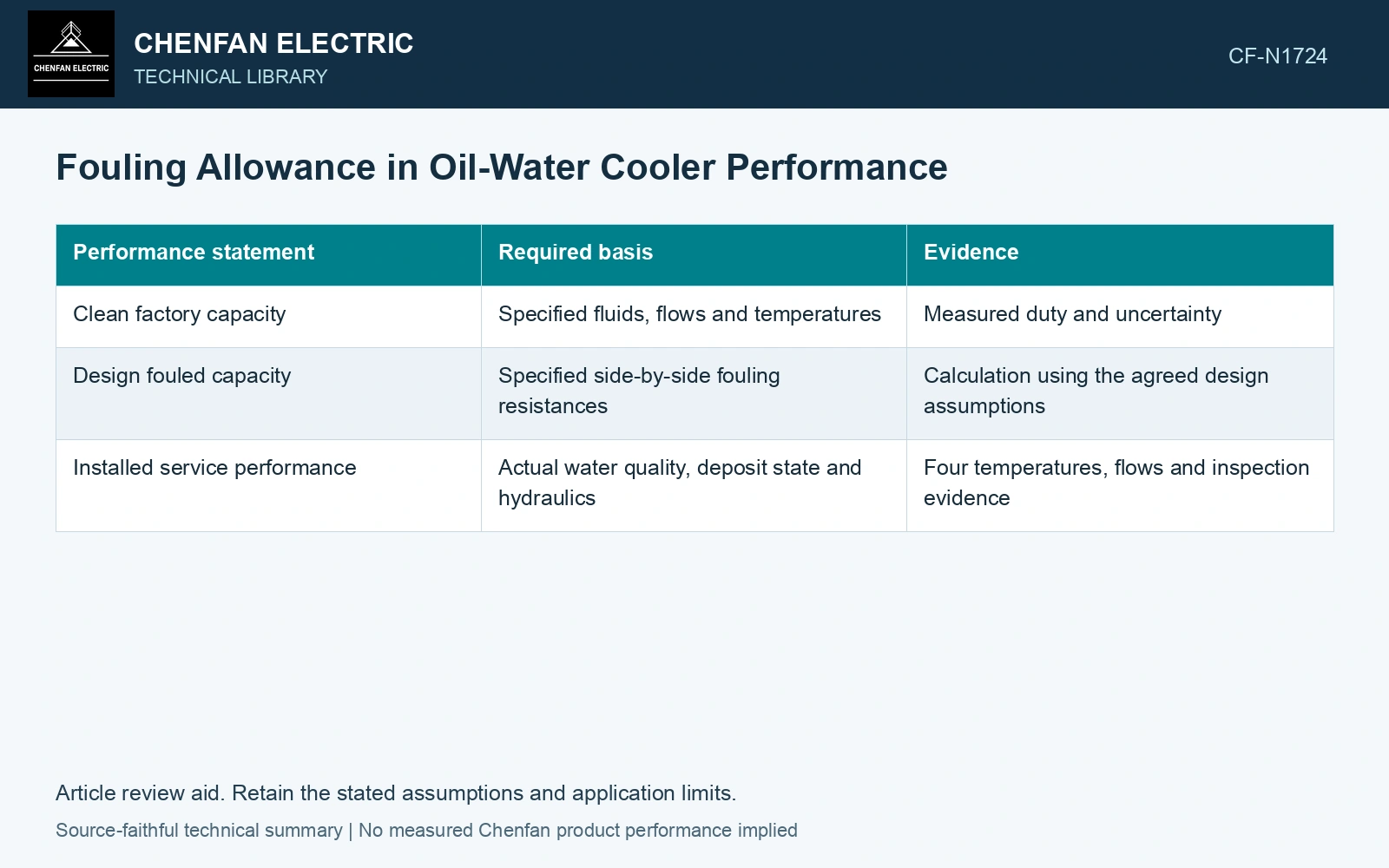
Define what the allowance covers
| Performance statement | Required basis | Evidence |
|---|---|---|
| Clean factory capacity | Specified fluids, flows and temperatures | Measured duty and uncertainty |
| Design fouled capacity | Specified side-by-side fouling resistances | Calculation using the agreed design assumptions |
| Installed service performance | Actual water quality, deposit state and hydraulics | Four temperatures, flows and inspection evidence |
A smaller U can have several causes
Record the water chemistry and expected maintenance conditions attached to the rating. Hardness, solids or biological growth can create different deposits and cleaning needs. “Suitable for cooling water” is not a sufficient water specification.
Maintenance evidence can distinguish a blocked flow path from loss of thermal performance: transformer guidance identifies debris and sludge in oil-water cooler tubes [2]. Check flow and obstruction before assigning the entire drop in apparent U to deposit resistance.
Carry fouling resistance into duty
Assume clean overall coefficient 500 W/(m²·K) on one consistent area basis and added fouling resistance 0.001 m²·K/W. Fouled U is 1/(1/500+0.001) = 333.3 W/(m²·K). For 10 m² and 20 K LMTD, duty falls from 100 to 66.67 kW if boundary temperatures remain fixed. Separate that prediction from a clean factory test.
References
- U.S. Department of Energy, DOE-HDBK-1012/2-92, Thermodynamics, Heat Transfer, and Fluid Flow, Volume 2, 1992.
- U.S. Bureau of Reclamation, FIST Volume 3-30, Transformer Maintenance, 2000.