

Current chopping and reignition are distinct parts of a reactor switching event. Chopping interrupts current before its natural zero and releases stored energy into the connected capacitances. Reignition restores a conducting path after dielectric recovery has begun, producing another fast transient. [1]
Define the breaker, reactor, connecting bus or cable and nearby capacitances. Record the event waveform rather than describing it with one overvoltage factor. A winding’s internal voltage distribution depends on rise time and frequency content as well as crest value.
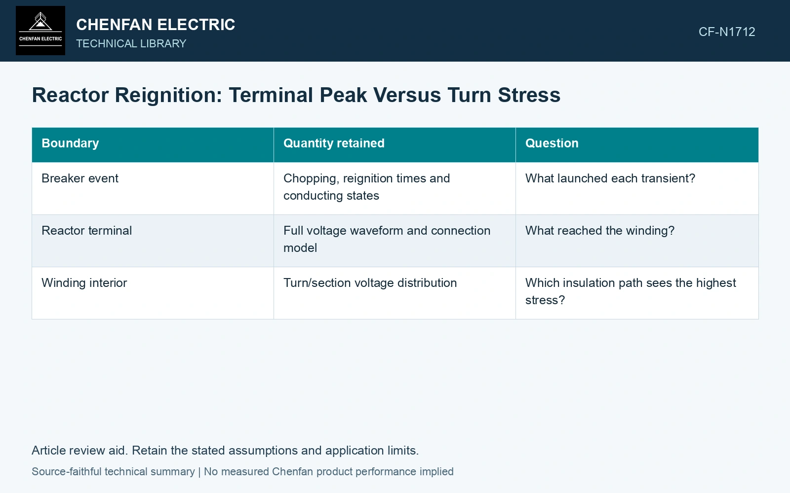
Track the stress through three boundaries
| Boundary | Quantity retained | Question |
|---|---|---|
| Breaker event | Chopping, reignition times and conducting states | What launched each transient? |
| Reactor terminal | Full voltage waveform and connection model | What reached the winding? |
| Winding interior | Turn/section voltage distribution | Which insulation path sees the highest stress? |
Use energy only as a screening check
For a lossless lumped screen with zero initial capacitor voltage and complete exchange, ½LI² = ½CVpk²; both sides are joules. This is an energy scale. With nonzero initial capacitor voltage, use the initial and final stored energies, not ½C times a voltage increment squared. Network coupling, damping and the breaker determine the actual waveform.
Popov and colleagues measured and modelled nonuniform fast-transient voltages within transformer windings. [2] Applying that principle to a reactor requires its own distributed winding parameters; it does not transfer their transformer’s stresses. Terminal crest and highest interturn stress must both be retained.
Record simultaneous terminal, section and turn-pair voltages from the reactor model so that peaks at different instants cannot be combined into a fictitious distribution.
Separate terminal peak from turn concentration
Assumptions: a specified switching-model instant has 100 kV across a 100-turn reactor and 20 kV across its first five turn intervals. Uniform sharing suggests 1 kV/turn, but those first intervals average 4 kV/turn, so at least one reaches 4 kV or more. An assumed 3 kV turn-interval operating-stress ceiling therefore fails by at least 1 kV, even though uniform division appears to pass. Hold that turn-insulation assignment and validate the actual winding response and protective scheme; the assumed inputs are not measured reactor data.
References
- H. Nie et al., Breaking Overvoltage of Dry-Type Air-Core Shunt Reactors and Its Cumulative Effect on the Interturn Insulation, IEEE Access 7, 55707–55720, 2019. DOI: 10.1109/ACCESS.2019.2913763.
- M. Popov, R. P. P. Smeets, L. van der Sluis, H. de Herdt and J. Declercq, Experimental and Theoretical Analysis of Vacuum Circuit Breaker Prestrike Effect on a Transformer, IEEE Transactions on Power Delivery 24, 2009. DOI: 10.1109/TPWRD.2009.2013383.