

An installed air-core reactor model needs linked fields and currents, rather than only one isolated-coil inductance. Field/circuit research demonstrates that coupling depends on coil geometry. [1] Extending that model to three phases requires the actual signed self/mutual matrix for the proposed layout.
Label phase positions and winding polarities. For a linear fixed geometry, write the flux linkage vector as λ = L i, where the diagonal entries are self-inductances and off-diagonal entries are signed mutual inductances. Use henries, amperes and weber-turns. Reciprocity normally gives Lij = Lji for the passive fixed system.
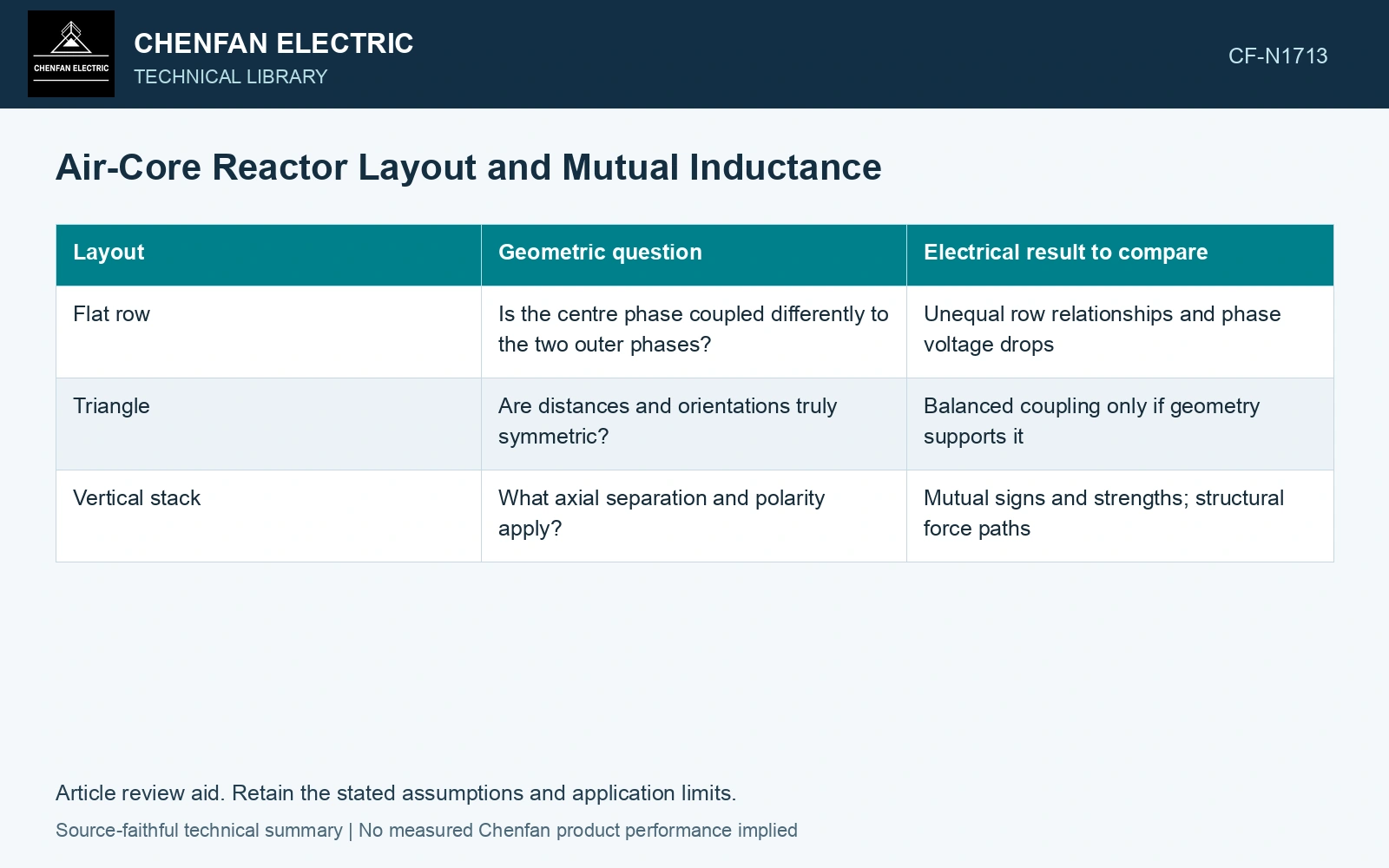
Compare the layout with a common matrix record
| Layout | Geometric question | Electrical result to compare |
|---|---|---|
| Flat row | Is the centre phase coupled differently to the two outer phases? | Unequal row relationships and phase voltage drops |
| Triangle | Are distances and orientations truly symmetric? | Balanced coupling only if geometry supports it |
| Vertical stack | What axial separation and polarity apply? | Mutual signs and strengths; structural force paths |
A symmetric example clarifies the sign
If each self-inductance is Ls and every mutual entry is M, balanced currents with ia + ib + ic = 0 give λa = (Ls − M)ia, and similarly for the other phases. This ideal result shows why mutual sign matters. It does not apply to an asymmetric layout without evaluating the full matrix.
Do not calculate a phase reactance from physical distance alone. Winding orientation, coil dimensions and nearby conductors affect coupling. The installed voltage drop should be derived from the matrix at the actual operating frequency.
For sinusoidal conditions, evaluate v = jωLi using the prescribed current phasors; the asymmetric layout need not have one scalar inductance for every phase. [2]
Compare the signed mutual-inductance effect
Assumptions: at 50 Hz, prescribed balanced phase currents are 100∠0°, 100∠−120° and 100∠120° A RMS. All self-inductances are 10 mH; signed Mab = Mbc = 1.0 mH and Mac = 0.2 mH. The full matrix gives phase voltage magnitudes 296.11, 282.74 and 296.11 V. Against an assumed 290 V drop ceiling, the outer phases fail by 6.11 V. A separate symmetric matrix with all mutuals +1.0 mH gives 282.74 V for every phase and passes. Qualify the actual layout; changing reference dots alone cannot turn every mutual sign independently. [2]
References
- J. Wu et al., Thermal Simulation and Analysis of Dry-Type Air-Core Reactors Based on Multi-Physics Coupling, Energies 16, 7456, 2023. DOI: 10.3390/en16217456.
- U.S. Department of Energy, DOE-HDBK-1011/3-92, Electrical Science, Volume 3, June 1992.