

In an LCC converter station, a valve-side winding can experience an AC waveform at a DC-shifted potential to earth. The offset depends on the bridge arrangement and the winding’s position in that arrangement. It cannot be assigned from the station pole voltage alone. Apply the HVDC transformer specification framework of IEC/IEEE 60076-57-129 to the stated liquid-immersed equipment [1].
Begin with a labelled bridge diagram. Give every winding terminal, valve connection and neutral or reference node an identifier. Set the earth reference explicitly, then describe each node potential as vk(t) = VDC,k + vAC,k(t). The terms are volts; the AC term may include harmonics. This is a bookkeeping decomposition, not an assertion that the waveform is sinusoidal.
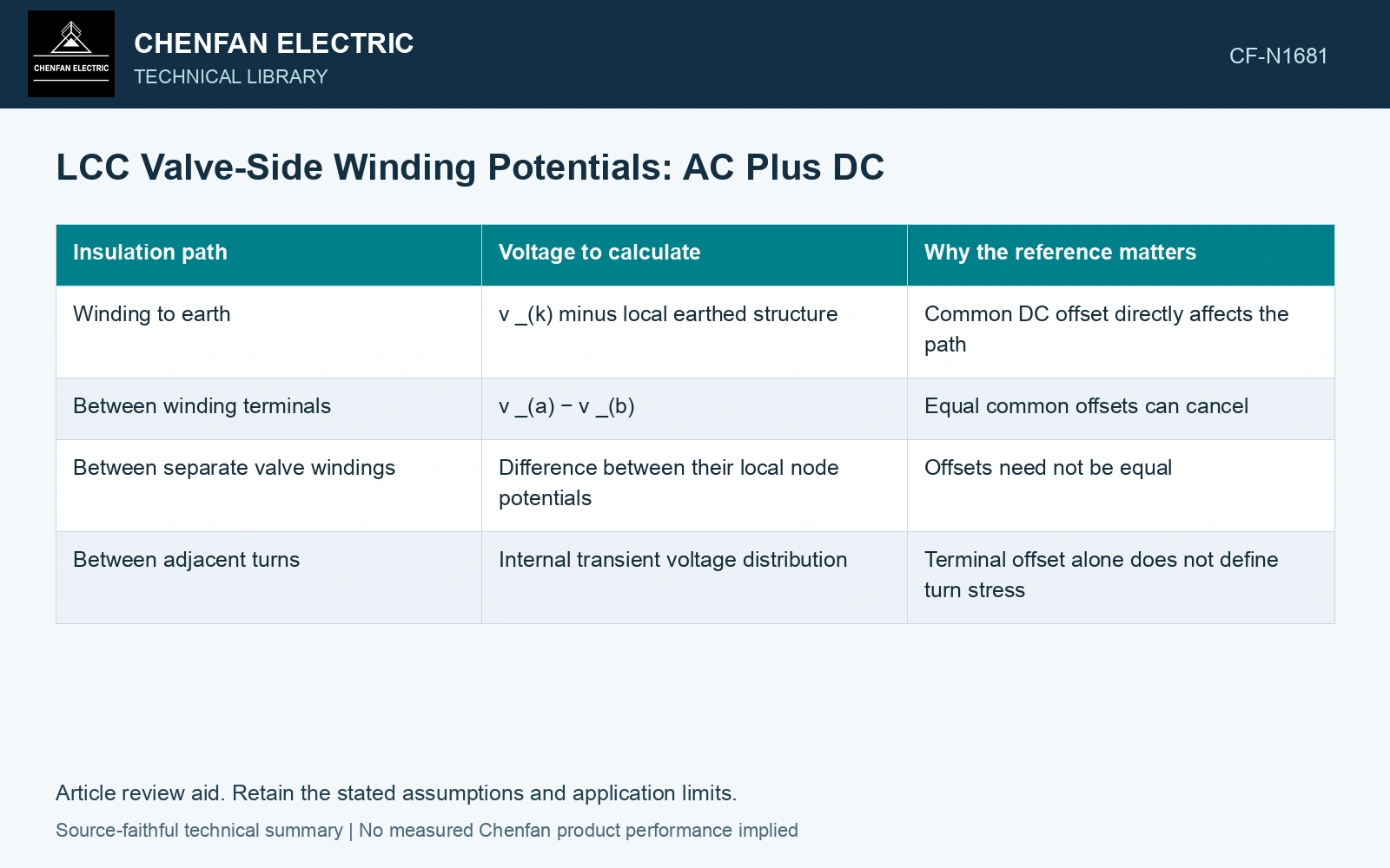
Subtract the correct two nodes
| Insulation path | Voltage to calculate | Why the reference matters |
|---|---|---|
| Winding to earth | vk minus local earthed structure | Common DC offset directly affects the path |
| Between winding terminals | va − vb | Equal common offsets can cancel |
| Between separate valve windings | Difference between their local node potentials | Offsets need not be equal |
| Between adjacent turns | Internal transient voltage distribution | Terminal offset alone does not define turn stress |
Where both endpoints share the same DC offset, that offset cancels from their differential voltage. It remains present in their stress to earth. Mixing these two paths can lead to an insulation diagram that applies the full pole voltage to every turn or ignores winding-to-earth duty.
Distinguish common offset from terminal difference
Assume instantaneous valve-terminal potentials of 350 kV and 250 kV to earth, each comprising the same +300 kV DC offset and opposite 50 kV AC samples. Terminal-to-terminal voltage is 350 − 250 = 100 kV; the pair common potential is (350 + 250)/2 = 300 kV. Assigning 300 kV to the terminal difference triples the actual sample, while omitting it from earth-related insulation misses the common offset. Label every insulation path by its two endpoints before transferring the node map into the field model.
Give each operating state its own map
Include normal operation, specified polarity changes, blocked states and relevant converter faults. Record the valve conduction or blocking assumptions and the connected station equipment. Capacitive coupling and transient voltage sharing can change the map during a fast event.
A steady potential decomposition helps identify insulation interfaces. It does not calculate local oil and pressboard fields, space charge or high-frequency winding distribution. Those require material properties, geometry and the relevant time history. [2]
Map the LCC node waveforms to their actual insulation paths before selecting a design stress. An MMC or other VSC station needs its own map: an LCC DC offset cannot be transferred merely because both projects carry the HVDC label.
References
- IEC/IEEE, IEC/IEEE 60076-57-129:2017, Power transformers – Part 57-129: Transformers for HVDC applications.
- CIGRE JWG A2/B4.28, Technical Brochure 406, HVDC Converter Transformers – Design review, test procedures, ageing evaluation and reliability in service, 2010.