

A GSU specification often combines a continuous rating with loosely described startup and abnormal duties. The missing link is the plant state diagram: which sources and loads are connected, for how long, and under what voltage and cooling conditions? Set the general power-transformer specification under IEC 60076-1 [1].
Assign a state ID to each defined connection. Begin with cold startup, reverse-fed auxiliaries, synchronization, normal generation, load rejection, trip recovery and planned isolation. Add other states only where the plant requires them. Use the approved single-line drawing to identify closed and open devices.
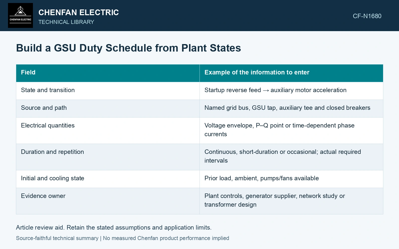
A working duty-schedule row
| Field | Example of the information to enter |
|---|---|
| State and transition | Startup reverse feed → auxiliary motor acceleration |
| Source and path | Named grid bus, GSU tap, auxiliary tee and closed breakers |
| Electrical quantities | Voltage envelope, P–Q point or time-dependent phase currents |
| Duration and repetition | Continuous, short-duration or occasional; actual required intervals |
| Initial and cooling state | Prior load, ambient, pumps/fans available |
| Evidence owner | Plant controls, generator supplier, network study or transformer design |
The example describes the shape of a record, not values to copy. A required quantity marked “unknown” is more useful than an invented duty. Give each unresolved input an owner and a date or design stage for resolution.
Separate a state from the transition into it
A no-load energized state may have modest current after settling, while the energization transition carries inrush. A post-trip auxiliary state may be small, while the transfer into it produces reacceleration current. Enter both where they affect equipment design.
Use appropriate data types. Balanced steady states need voltage, P and Q; faults and switching events need waveforms or a defined dynamic study. Repeated operations need thermal history. A single MVA figure cannot substitute for all three.
Populate one transition row with current and duration
Assume a 50 Hz startup record with winding current 0.60 pu for 30 s followed by 1.50 pu for 5 s, on one fixed rated-current base. Its normalized heating integral is 0.60² × 30 + 1.50² × 5 = 22.05 pu²s; equivalent RMS over 35 s is √(22.05/35) = 0.794 pu. That average conceals a 1.50 pu stage. Put both intervals in the duty schedule and retain the short-duration current for voltage and force checks rather than rating the start from the equivalent average alone.
Resolve conflicting assumptions before tendering
Compare each row with generator capability, grid voltage requirements and auxiliary-supply logic. If the generator supplier assumes one tap and the network study another, the calculations do not describe a common plant. Update the state record, then rerun the affected cases.
Separate required operating duties from contingencies that depend on protection action. For each duty, the connection and duration determine the electrical and thermal case. An abnormal event in a study must not quietly become permission for continuous operation.
For mineral-oil equipment, relate the loading assessment to operating temperature and thermal ageing [2].
References
- IEC, IEC 60076-1:2011, Power transformers – Part 1: General.
- IEC, IEC 60076-7:2018, Power transformers – Part 7: Loading guide for mineral-oil-immersed power transformers.