

When a generator loses excitation, falling active power does not guarantee falling GSU current. The machine may absorb reactive power from the system while its rotor and terminal voltage evolve. The transformer responds to the current through its actual connection, not to the MW trend alone. Set the general power-transformer specification under IEC 60076-1 [1].
For a balanced, slowly varying portion of the event, I = √(P² + Q²)/(√3 V). With P in watts, Q in vars and V in line-to-line RMS volts, the result is amperes. Apply it to time-aligned measurements at the same terminal. During rapid or unbalanced transients, use recorded phase currents and the appropriate dynamic model.
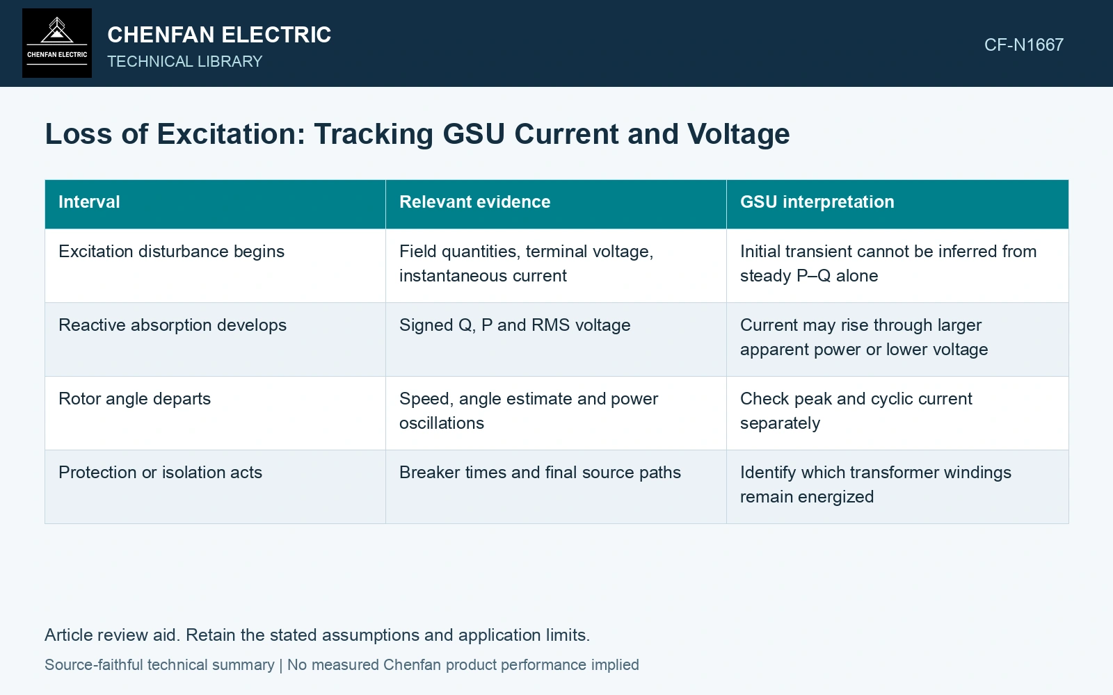
Separate the event into observable intervals
| Interval | Relevant evidence | GSU interpretation |
|---|---|---|
| Excitation disturbance begins | Field quantities, terminal voltage, instantaneous current | Initial transient cannot be inferred from steady P–Q alone |
| Reactive absorption develops | Signed Q, P and RMS voltage | Current may rise through larger apparent power or lower voltage |
| Rotor angle departs | Speed, angle estimate and power oscillations | Check peak and cyclic current separately |
| Protection or isolation acts | Breaker times and final source paths | Identify which transformer windings remain energized |
These are interpretive intervals rather than a promised sequence. Their duration and even their presence depend on the generator, network strength, protection and controls. Do not substitute a generic timeline for the plant’s event record.
A simple counterexample to the MW assumption
Assume balanced 50 Hz points on one power base: initially P = 0.8 pu, Q = 0 and V = 1.00 pu, giving current 0.800 pu. Later P = 0.6 pu, Q = −0.7 pu and V = 0.90 pu give current √(0.6² + 0.7²)/0.90 = 1.024 pu, 28.05% higher despite lower MW. Use the later measured current and its duration in transformer duty assessment; the arithmetic does not establish permission for loss-of-excitation operation.
Do not combine generator and transformer limits
The generator’s loss-of-excitation protection addresses machine and system consequences. Transformer thermal and mechanical checks use the current waveform, duration and cooling condition. A generator relay setting is therefore not a transformer overload curve.
For a post-event review, plot terminal voltage, P, Q and each phase current on one clock. Add the generator and grid breaker transitions. Check transformer currents before discussing thermal recovery. If only slow supervisory data exist, state that short peaks and the early transient remain unresolved rather than reconstructing them from a low-resolution MW record.
For mineral-oil equipment, relate the loading assessment to operating temperature and thermal ageing [2].
References
- IEC, IEC 60076-1:2011, Power transformers – Part 1: General.
- IEC, IEC 60076-7:2018, Power transformers – Part 7: Loading guide for mineral-oil-immersed power transformers.