

A pumped-storage transformer carries power in opposite directions during pumping and generation. Its conductor heating still depends mainly on current, while its voltage drop changes with the signed active and reactive power. The two operating envelopes should be calculated separately. Set the general power-transformer specification under IEC 60076-1 [1].
Choose a sign convention at one terminal: positive P for export and positive Q for reactive supply. Plot pumping at negative P and generation at positive P. Do not reverse Q automatically with P; excitation and system requirements define the reactive range in each mode.
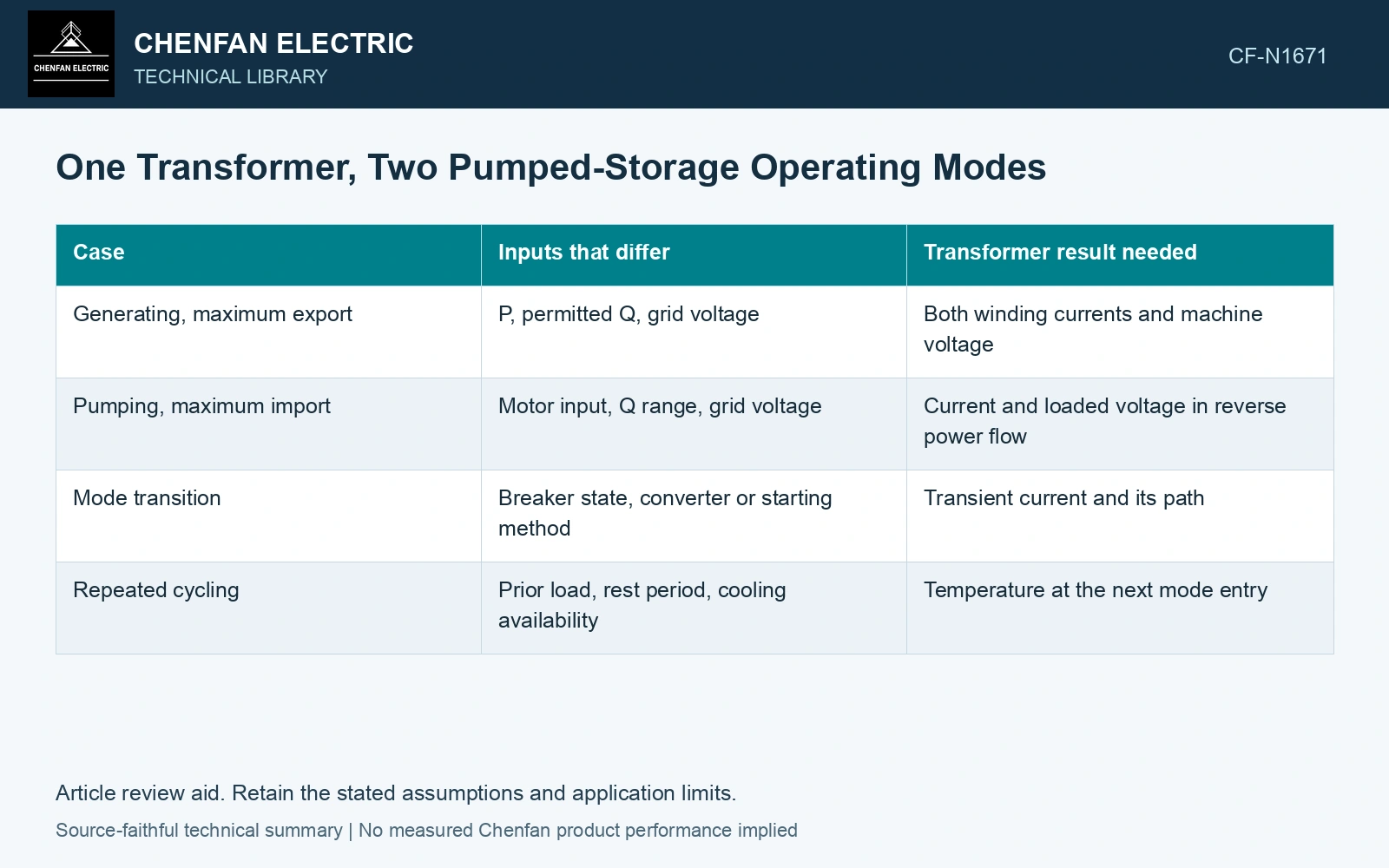
Compare the endpoints on a common base
| Case | Inputs that differ | Transformer result needed |
|---|---|---|
| Generating, maximum export | P, permitted Q, grid voltage | Both winding currents and machine voltage |
| Pumping, maximum import | Motor input, Q range, grid voltage | Current and loaded voltage in reverse power flow |
| Mode transition | Breaker state, converter or starting method | Transient current and its path |
| Repeated cycling | Prior load, rest period, cooling availability | Temperature at the next mode entry |
At balanced sinusoidal steady state, I = √(P² + Q²)/(√3 V), using watts, vars and line-to-line volts. Equal magnitudes of P and Q at equal voltage give equal RMS current, regardless of the sign of P. That observation says nothing about transient starting current, regulation or differences in cooling.
Compare equal power magnitudes with signed regulation
Assume a 100 MVA base, 1.00 pu terminal voltage and 50 Hz balanced service. Generating at P = +0.8 pu, Q = +0.3 pu and pumping at P = −0.8 pu, Q = +0.3 pu both give current √(0.8² + 0.3²) = 0.854 pu. For a first-order machine-to-grid voltage-rise convention with R = 0.01 pu and X = 0.10 pu, the first-order signed voltage-drop terms RP + XQ are 0.038 pu and 0.022 pu. Use the actual terminal sign mapping in load flow: equal current does not mean identical regulation or a reset thermal state.
The voltage case can reverse while the hot spot persists
Use phasor load flow with the actual tap and winding connection. A tap suitable for export at low grid voltage may constrain motor-mode voltage at the opposite envelope. For variable-speed systems, define the converter connection and use its actual transformer current spectrum.
A mode change does not reset temperature. Preserve the oil and winding thermal state from the previous cycle. A short no-load interval may leave most stored heat in the active part even when the power meter approaches zero. If the transformer remains energized, core losses continue.
Pumping and generation share a thermal history even when their electrical endpoints differ. Apply the daily dwell times to the worst sustained current in each mode and the credible transition. A separate rating check for each steady state can miss the temperature inherited from the previous one.
For mineral-oil equipment, relate the loading assessment to operating temperature and thermal ageing [2].
References
- IEC, IEC 60076-1:2011, Power transformers – Part 1: General.
- IEC, IEC 60076-7:2018, Power transformers – Part 7: Loading guide for mineral-oil-immersed power transformers.