

A generator can remain inside its capability curve while its generator step-up transformer exceeds a winding-current limit. The mismatch usually appears when a dispatch discussion uses megawatts and treats reactive power as a separate matter. Both travel through the transformer. Set the general power-transformer specification under IEC 60076-1 [1].
For a balanced three-phase operating point, apparent power is S = √(P² + Q²), and terminal current is I = S/(√3 V). Use P in watts, Q in vars, V as line-to-line RMS volts and I in amperes. These relations assume sinusoidal steady operation; they do not describe an unbalanced fault or harmonic heating.
Draw the transformer boundary at the actual voltage
If the low-voltage winding permits current ILV, its current boundary on the P–Q plane is P² + Q² ≤ 3VLV²ILV². Lower terminal voltage shrinks this circle. A constant MVA circle drawn at nameplate voltage can therefore hide a low-voltage current problem.
The high-voltage winding needs its own check. Use the grid-side voltage and include losses and the actual tap ratio when translating the operating point. The generator capability curve may depend on terminal voltage, cooling conditions and excitation limits. Overlaying a single curve without those conditions gives a false intersection.
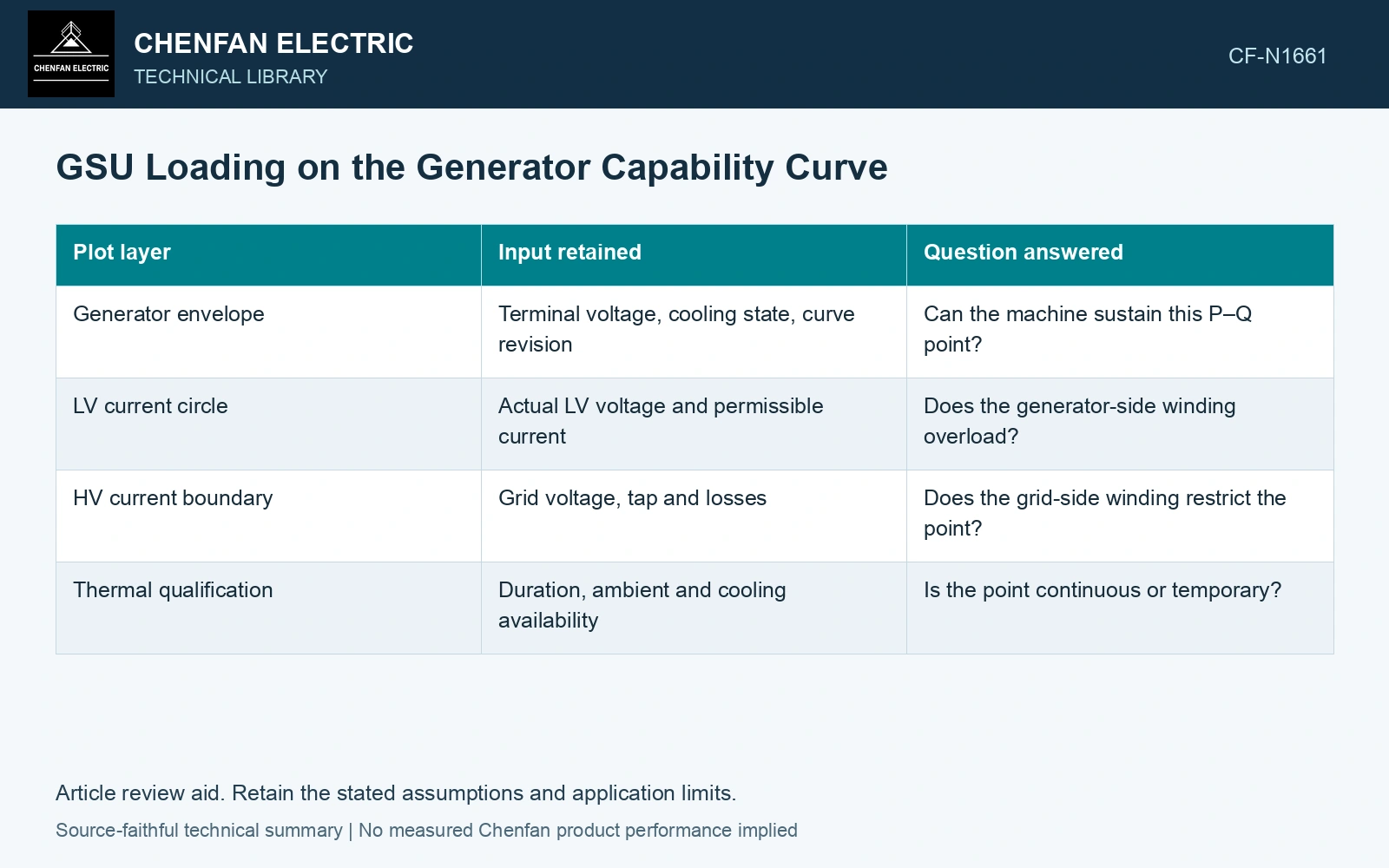
A plotting record that exposes the mismatch
| Plot layer | Input retained | Question answered |
|---|---|---|
| Generator envelope | Terminal voltage, cooling state, curve revision | Can the machine sustain this P–Q point? |
| LV current circle | Actual LV voltage and permissible current | Does the generator-side winding overload? |
| HV current boundary | Grid voltage, tap and losses | Does the grid-side winding restrict the point? |
| Thermal qualification | Duration, ambient and cooling availability | Is the point continuous or temporary? |
Assume balanced 50 Hz service at P = 90 MW, Q = 40 Mvar and LV voltage 19.0 kV. Apparent power is √(90² + 40²) = 98.49 MVA and current is 2993 A. An assumed 2900 A continuous LV limit allows only √3 × 19 × 2.9 = 95.44 MVA at that voltage. The requested point exceeds the current boundary by about 93 A even though its apparent power is below 100 MVA. Exclude that point or establish an approved revised envelope.
Read the intersection before selecting a rating
Evaluate maximum export, maximum reactive supply, maximum reactive absorption and the lowest permitted terminal voltage. Identify which device defines each edge of the feasible region. A generator rotor limit and a transformer winding limit can meet at the same point for different reasons.
At an excluded dispatch point, identify the binding current, voltage or thermal constraint on the plot. A larger headline MVA rating may leave the voltage envelope, connections or cooling duty unresolved; revise the constraint that actually excludes the point.
For mineral-oil equipment, relate the loading assessment to operating temperature and thermal ageing [2].
References
- IEC, IEC 60076-1:2011, Power transformers – Part 1: General.
- IEC, IEC 60076-7:2018, Power transformers – Part 7: Loading guide for mineral-oil-immersed power transformers.