

Backfeeding a generator step-up transformer means importing power from the transmission system through a transformer normally used for export. The windings can transfer power in either direction, but the plant connection may energize equipment that the startup procedure expects to be isolated. Keep the selected winding arrangement within the general power-transformer specification framework [1].
Start at the grid breaker and follow every conducting connection to the auxiliary load. Mark the generator circuit breaker, auxiliary-transformer tee, disconnectors and earth switches. A tee on the transformer side of an open generator breaker behaves very differently from a tee on the machine side.
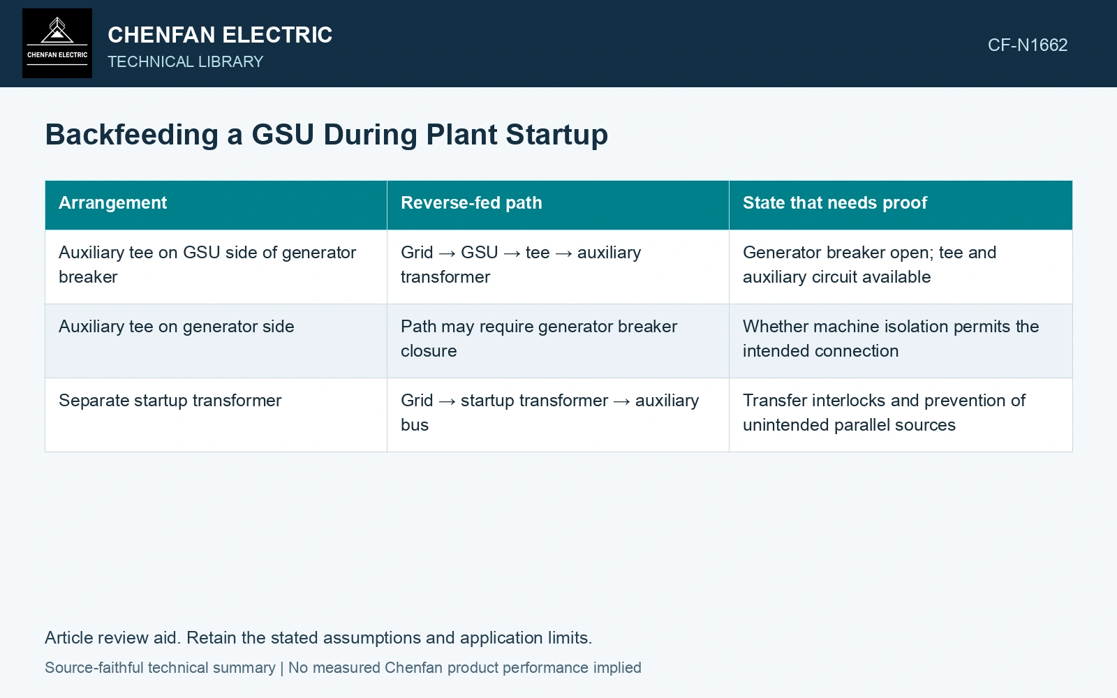
Two breaker arrangements, two startup paths
| Arrangement | Reverse-fed path | State that needs proof |
|---|---|---|
| Auxiliary tee on GSU side of generator breaker | Grid → GSU → tee → auxiliary transformer | Generator breaker open; tee and auxiliary circuit available |
| Auxiliary tee on generator side | Path may require generator breaker closure | Whether machine isolation permits the intended connection |
| Separate startup transformer | Grid → startup transformer → auxiliary bus | Transfer interlocks and prevention of unintended parallel sources |
Use this table to review the drawing; operating staff need the approved switching procedure. Actual isolation and energization must follow the plant’s approved procedure. A stopped generator is an operating condition; an open, secured isolating boundary is a separate condition.
Calculate the voltage in the direction being used
For a first-pass no-load check, VLV ≈ VHV/a, where a is the selected line-voltage ratio for the stated vector connection. Use volts on both sides. Then include transformer regulation, auxiliary-transformer ratio and cable drop to estimate the loaded auxiliary-bus voltage.
A tap selected for full-load export may produce a poor startup bus voltage when the imported load is small. Check the highest and lowest grid voltages, motor acceleration demand and the available tap positions. Distinguish a de-energized tap selection from an on-load adjustment; their operating permissions differ.
Screen the reverse-fed auxiliary voltage range
Assume 50 Hz operation, GSU line-voltage ratio 20 and auxiliary-transformer ratio 20/6.6. Ignoring drops, grid endpoints of 380 and 420 kV produce auxiliary voltages of 6.27 and 6.93 kV. Against an assumed required steady band of 6.3–6.9 kV, each endpoint misses by 0.03 kV. Reject that fixed-ratio screen, then include load-flow drops, motor acceleration and the actual allowed tap changes. This calculation describes connected buses and does not authorize a switching sequence.
Keep energization and load checks separate
The initial GSU energization can produce magnetizing inrush. Subsequent motor starting adds a different current duty through the transformer and supply impedance. Combining these as one unspecified “startup current” makes protection and voltage studies harder to interpret.
Retain three cases: GSU energization with downstream breakers open; auxiliaries running before motor acceleration; and the largest credible starting group. Record which breakers are closed in each case and whether the generator terminals can acquire voltage. The reverse-feed assessment is complete only when the single-line state, voltage calculation and operating procedure describe the same connection.
Verify the selected terminal ratio with a test method matched to the winding connection [2].
References
- IEC, IEC 60076-1:2011, Power transformers – Part 1: General.
- Ohlen, M., and Werelius, P., A Guide to Transformer Ratio Measurements, Megger Sweden, 2010-01-18, Definitions and TTR measurements.