

A converter control upgrade can change how an existing rectifier transformer is used. Faster regulation, a different firing pattern or a new minimum-load strategy may alter winding current even when nominal DC power and hardware remain unchanged. IEC 61378-1 covers industrial converter-transformer specification, design and testing [1].
Compare the actual old and proposed control behavior over the same required output range. Keep transformer connection, source conditions and measurement definitions consistent so that the effect belongs to the control change.
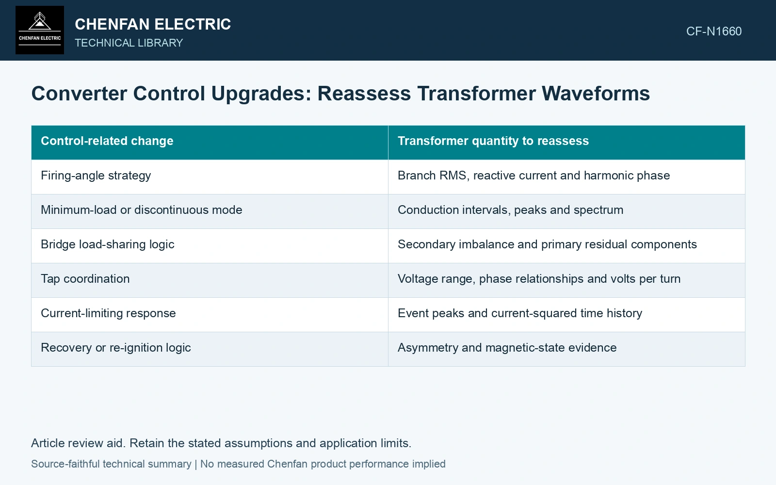
Compare waveform envelopes
| Control-related change | Transformer quantity to reassess |
|---|---|
| Firing-angle strategy | Branch RMS, reactive current and harmonic phase |
| Minimum-load or discontinuous mode | Conduction intervals, peaks and spectrum |
| Bridge load-sharing logic | Secondary imbalance and primary residual components |
| Tap coordination | Voltage range, phase relationships and volts per turn |
| Current-limiting response | Event peaks and current-squared time history |
| Recovery or re-ignition logic | Asymmetry and magnetic-state evidence |
Include steady conditions, transitions and approved abnormal-event cases. A better average output regulation result does not establish a lower worst-case winding current.
Keep different rating questions separate
RMS current supports resistive heating, while harmonic distribution affects frequency-dependent losses. Peak and transient current contribute to mechanical and event duty. Voltage history governs magnetic excitation under the appropriate winding model. One unchanged terminal MVA number does not resolve all these quantities.
Compare synchronized branch waveforms rather than only controller setpoints. A commanded current limit and its actual achieved response can differ during the interval that matters to the transformer.
For magnetic bias concerns, examine the corrected induced-voltage integral and internal current symmetry. Do not label every new current peak a core-flux problem.
Check time spent in each state
An upgrade can increase operation at a particular low-load or regulating condition. Even if that state’s instantaneous loss is unchanged, its contribution to accumulated energy or thermal cycling can increase. Use the intended duty schedule and cooling state.
Reserve tests or operating conditions to challenge the revised model. Calibrating the new waveform estimate to one favorable rated point cannot establish its transition or minimum-load envelope.
Compare control revisions on one conductor-loss basis
Assume old and revised steady winding RMS currents of 1000 A and 1050 A at the same 75 °C resistance of 0.010 Ω. Resistive losses are 10.000 and 11.025 kW, a 10.25% increase. If the revised state persists for 2000 h, its extra resistive energy is 2050 kWh. Keep that increment separate from frequency-dependent additional losses, then test the proposed waveform and thermal state against the retained envelope. Unchanged DC power cannot clear a measured 5% increase in winding RMS current.
Resolve changed duties explicitly
Classify each output as within the verified envelope, requiring a revised assessment, or unresolved because evidence is missing. Use equipment-specific engineering where the new control exceeds or changes a qualification premise.
Approve the revised control against measured or validated waveform envelopes, including transitions and minimum load. Any changed RMS current, harmonic spectrum, fault response or excitation history needs its own transformer assessment, even when nominal power is unchanged.
Check ratio and phase on the actual special connection and selected tap [2].
References
- IEC, IEC 61378-1:2011, Converter transformers – Part 1: Transformers for industrial applications.
- Gandhi Jeyaraj, S., Milne, R., and Mitchell, G., On-Site Testing of Special Transformers, Megger technical paper, Sections 2–6.