

An electrode short changes the DC circuit rapidly, but the converter and transformer do not experience one unchanging fault state. Source-fed current, control limiting and stored-energy discharge can occupy different intervals and paths. IEC 61378-1 covers industrial converter-transformer specification, design and testing [1].
Define the actual furnace, rectifier and DC-reactor connection. Obtain the relevant controller and protection response evidence. Do not assume that a commanded current limit or blocking event occurs instantly or removes every current path.
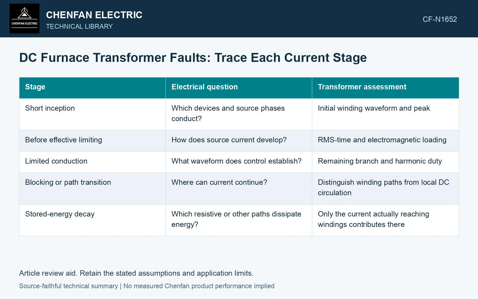
Build the event timeline
| Stage | Electrical question | Transformer assessment |
|---|---|---|
| Short inception | Which devices and source phases conduct? | Initial winding waveform and peak |
| Before effective limiting | How does source current develop? | RMS-time and electromagnetic loading |
| Limited conduction | What waveform does control establish? | Remaining branch and harmonic duty |
| Blocking or path transition | Where can current continue? | Distinguish winding paths from local DC circulation |
| Stored-energy decay | Which resistive or other paths dissipate energy? | Only the current actually reaching windings contributes there |
Use measured or validated timing for the actual system. Use the stages that occur in the actual furnace converter.
Keep the reactor energy in the circuit
An ideal reactor initially carrying ID stores E = ½LID², with inductance L in henries, current in amperes and energy in joules. Its current cannot disappear without an appropriate voltage-time and energy path.
That stored energy is not automatically dissipated in the transformer. Trace the continuing conduction and freewheel paths. A local DC path may carry a significant tail while transformer current has changed substantially; another arrangement may keep source-linked conduction active.
For an approximately resistive winding loss estimate, energy over the event is ∫R i²(t)dt using the actual winding branch current and a justified resistance. Peak force and frequency-dependent losses require additional treatment. A DC-bus current trace alone cannot supply every winding’s event duty.
Keep reactor storage distinct from winding dissipation
Assume a DC reactor of 20 mH at 10 kA: stored energy is 0.5 × 0.020 × 10,000² = 1.00 MJ. Separately assume a winding branch carries 3 kA for 0.10 s with resistance 0.002 Ω; its resistive energy is 0.002 × 3000² × 0.10 = 1.8 kJ. These are different energy records. The winding figure is only 0.18% of the initial reactor storage and cannot identify where the rest is dissipated. Trace freewheel, source-fed and decay paths before assigning the electrode-short duty.
Compare several credible initial states
Initial current, firing state, source voltage and network impedance can change the response. Evaluate the approved event envelope rather than one favorable simulation. Include repeat-event assumptions separately where cumulative thermal duty matters.
Verify current and energy balance through transitions. A model that removes an inductor current at blocking without an energy path can understate the event severely.
Identify the stage and winding that govern the event assessment, and separate the post-event current confined to the DC circuit. Preserve the measured or validated source-fed interval even when the controller later limits or blocks conduction.
Retain an explicit measurement model and input uncertainties when comparing measured and calculated duty [2].
References
- IEC, IEC 61378-1:2011, Converter transformers – Part 1: Transformers for industrial applications.
- JCGM, JCGM 100:2008, Evaluation of measurement data — Guide to the expression of uncertainty in measurement, 2008.