

Arc re-ignition changes the DC load and rectifier conduction. The transformer may experience a large current transient while its main alternating excitation remains primarily determined by the voltage across its magnetizing branch. Current magnitude alone cannot establish flux bias. IEC 61378-1 covers industrial converter-transformer specification, design and testing [1].
Record the AC voltages, phase currents, converter state and DC event on a synchronized time base. Separate the source excitation from the voltage drops associated with the changed current.
Reconstruct the magnetic quantity
Under a uniform linked-flux approximation, vind = NA dB/dt. Thus B(t) − B(t0) = (1/NA)∫vind dt, with effective area A in square metres, turn count N, voltage in volts and flux density in teslas.
The induced voltage is not always equal to measured terminal voltage. Resistance and leakage-related drops can matter during a rapid load change. Use an appropriate winding model or qualified flux-related measurement instead of integrating an uncorrected voltage trace automatically.
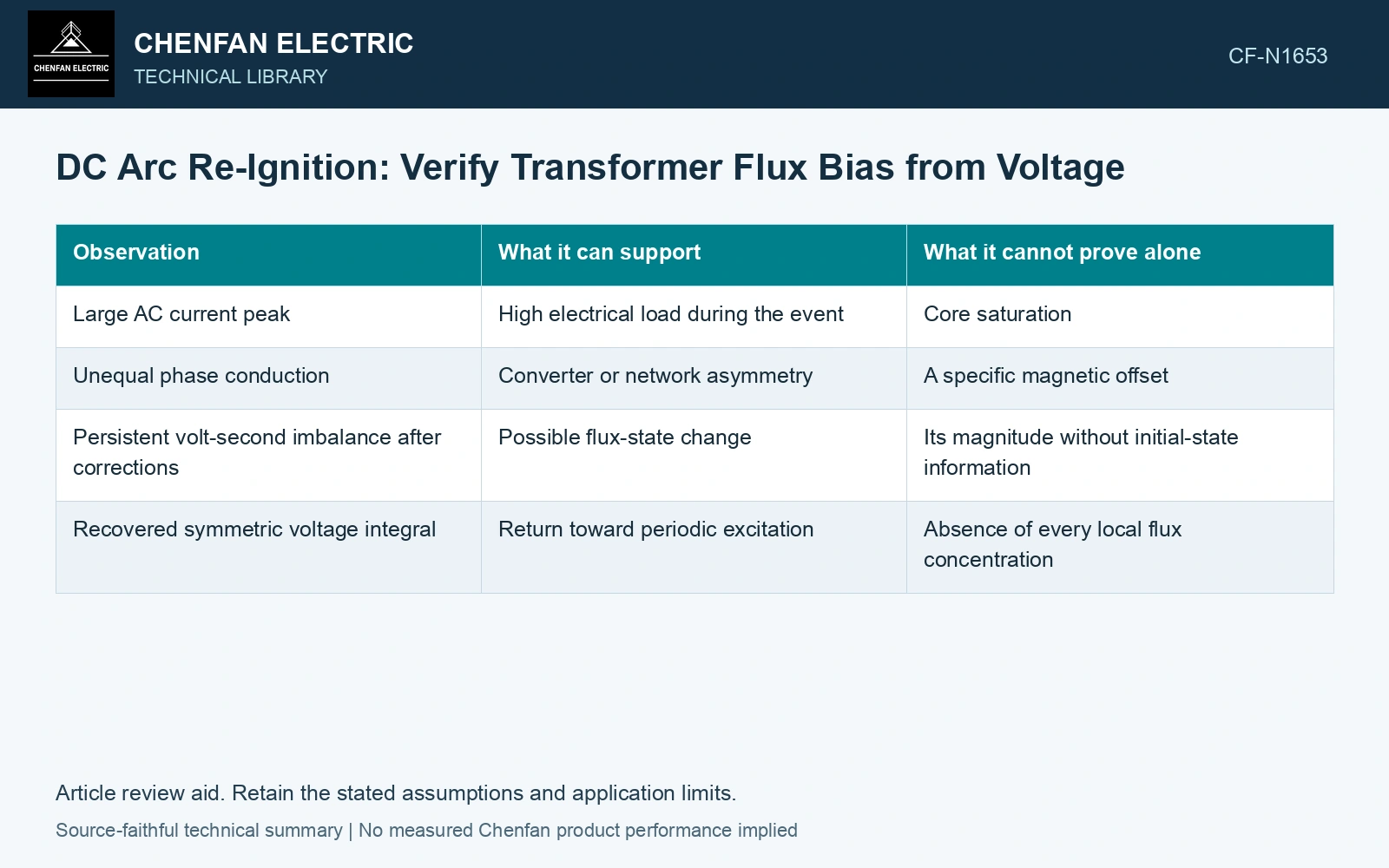
| Observation | What it can support | What it cannot prove alone |
|---|---|---|
| Large AC current peak | High electrical load during the event | Core saturation |
| Unequal phase conduction | Converter or network asymmetry | A specific magnetic offset |
| Persistent volt-second imbalance after corrections | Possible flux-state change | Its magnitude without initial-state information |
| Recovered symmetric voltage integral | Return toward periodic excitation | Absence of every local flux concentration |
Control integration errors
Sensor offset accumulates into a false flux drift. Establish the voltage reference, bandwidth and offset behavior, and compare pre-event and recovered periodic records. Do not remove a genuine low-frequency component merely to make the integral close.
Initial flux matters. The integral determines change from B(t0); it does not independently measure the absolute starting value. Retain magnetic preparation or a justified initial-state estimate when absolute peak flux is the question.
Quantify how voltage offset contaminates flux change
Assume a linked-flux screening path with 100 turns and effective area 0.10 m². A corrected mean induced-voltage excess of 2 V over 50 ms gives ΔB = 2 × 0.050/(100 × 0.10) = 0.010 T. An uncorrected sensor offset of 0.2 V adds a false 0.001 T, 10% of that change. Establish offset and initial flux before attributing a reconstructed drift to re-ignition; use the converter current paths to distinguish load current from magnetizing response.
Connect asymmetry to the circuit
If current conduction becomes asymmetric, determine how the winding ampere-turns and terminal voltages respond. A tertiary or shared connection can alter the internal balance. The DC output event should be mapped through the actual rectifier-transformer topology.
Compare modeled or measured magnetic excitation with the current transient over the same interval. If the current rises while corrected magnetic excitation remains within the established envelope, investigate load and leakage duty rather than labeling the core saturated.
If a flux-offset hypothesis survives, check it against additional magnetic or excitation evidence and the model’s local limitations. One average linked-flux reconstruction does not describe every joint region.
State whether the corrected voltage-time record supports a changed magnetic state during re-ignition. If it does not, follow the observed current change through the converter and circuit response before assigning a saturation mechanism.
Retain an explicit measurement model and input uncertainties when comparing measured and calculated duty [2].
References
- IEC, IEC 61378-1:2011, Converter transformers – Part 1: Transformers for industrial applications.
- JCGM, JCGM 100:2008, Evaluation of measurement data — Guide to the expression of uncertainty in measurement, 2008.