

A current-doubler output uses two branch currents to supply the load. The transformer secondary participates in particular charging intervals, while other paths may carry freewheeling current. The output-current label therefore does not establish the secondary conductor’s RMS duty. IEC 61378-1 covers industrial converter-transformer specification, design and testing [1].
Draw the actual converter connection and identify every conducting state. Use the current in the transformer branch, not just the currents entering the DC output node.
Define a simple waveform explicitly
For an assumed arrangement, suppose inductor currents I1 and I2 have negligible ripple. The secondary carries +I1 for fraction d1 of a period, −I2 for fraction d2, and zero otherwise. Then IS,rms² = d1I1² + d2I2², with d1 + d2 ≤ 1. Assume the DC load receives Iout = I1 + I2 under the specified steady connection.
With balanced I1 = I2 = 150 A and d1 = d2 = 0.5, the illustrative output is 300 A and secondary RMS is 150 A. This demonstrates the current mapping only; it does not specify a converter voltage ratio, efficiency or hardware rating.
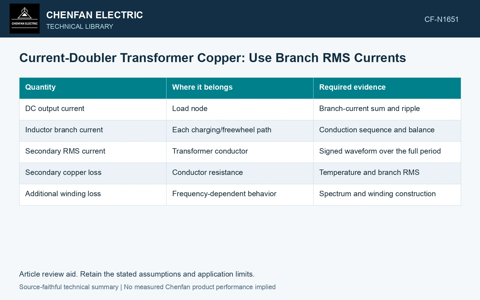
| Quantity | Where it belongs | Required evidence |
|---|---|---|
| DC output current | Load node | Branch-current sum and ripple |
| Inductor branch current | Each charging/freewheel path | Conduction sequence and balance |
| Secondary RMS current | Transformer conductor | Signed waveform over the full period |
| Secondary copper loss | Conductor resistance | Temperature and branch RMS |
| Additional winding loss | Frequency-dependent behavior | Spectrum and winding construction |
Check balance rather than assuming it
Actual inductor currents can differ because of control, component or circuit asymmetry. Recalculate the waveform and its mean as well as its RMS. If the simplified alternating model produces a nonzero average secondary current, investigate whether its assumed states can represent a valid periodic operating condition and how the circuit responds.
Inductor volt-second balance is another check. A periodic current state requires an appropriate net voltage relationship; arbitrary branch currents cannot simply be inserted into an otherwise balanced model.
Include ripple and commutation intervals when they materially affect duty. The constant-current approximation may be useful for screening, but its error should be checked against a detailed or measured waveform.
Compare loss only after matching the output duty
Assume two voltage-qualified candidate windings serving the same DC output: the current-doubler branch carries 150 A RMS with resistance 4 mΩ at 75 °C, while the alternative carries 300 A RMS with resistance 1 mΩ at 75 °C. Each gives I²R = 90 W. Halving RMS current therefore yields no resistive-loss reduction in this assumed geometry. Compare the qualified winding resistance and additional losses, not the output-current label, before claiming improved copper utilization.
Compare copper on an equivalent electrical duty
Copper loss is I²R for the appropriate RMS branch current and resistance under the stated assumptions. A lower current can accompany a different voltage, turn count or conductor length. It does not by itself prove lower copper requirement than another rectifier arrangement.
Compare copper utilization at matched output duty using each winding’s RMS current, resistance and additional losses. The current-doubler relationship establishes how branch currents combine at the output; conductor geometry and thermal duty still require their own comparison.
Retain an explicit measurement model and input uncertainties when comparing measured and calculated duty [2].
References
- IEC, IEC 61378-1:2011, Converter transformers – Part 1: Transformers for industrial applications.
- JCGM, JCGM 100:2008, Evaluation of measurement data — Guide to the expression of uncertainty in measurement, 2008.