

A transformer tap changes the AC supply relationship over its permitted operating process. Converter firing control changes conduction more quickly. Coordinating them requires a map of reachable DC voltage and internal current duty, not merely a tap range and a maximum firing-angle value. IEC 61378-1 covers industrial converter-transformer specification, design and testing [1].
Define the converter topology, load behavior and permitted control regions. Some bridges support operating modes that others do not; a generic cosine expression cannot authorize those modes.
Build one operating slice at a time
For an ideal fully controlled bridge in a specified continuous-current regime, write VDC = VDC0(k) cos α, where k identifies the tap, VDC0 its ideal zero-angle output and α the firing angle. This is a screening relation. Commutation overlap, resistance and device drops alter the actual output.
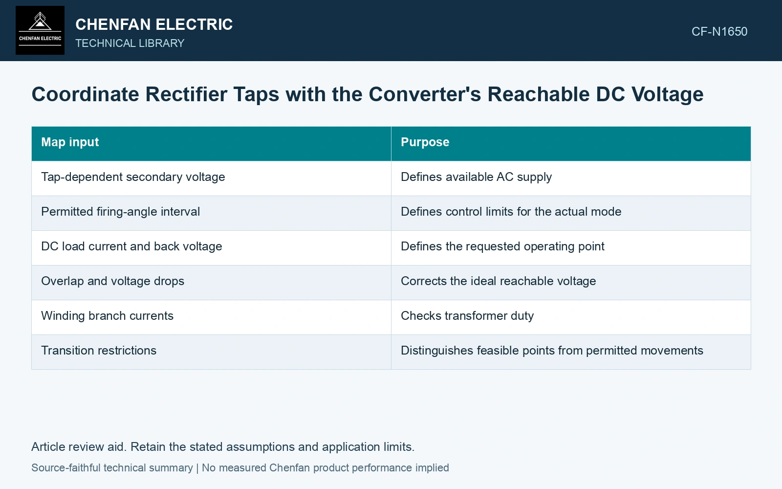
| Map input | Purpose |
|---|---|
| Tap-dependent secondary voltage | Defines available AC supply |
| Permitted firing-angle interval | Defines control limits for the actual mode |
| DC load current and back voltage | Defines the requested operating point |
| Overlap and voltage drops | Corrects the ideal reachable voltage |
| Winding branch currents | Checks transformer duty |
| Transition restrictions | Distinguishes feasible points from permitted movements |
For each tap, calculate the DC voltage interval reachable at the permitted angles and load states. Mark points excluded by current, thermal, commutation or device limits. A voltage that is mathematically reachable can still be outside the qualified duty envelope.
Compare control effort at the same output
Two tap-angle combinations can produce similar DC voltage with different reactive demand and current waveforms. Evaluate those consequences using the actual circuit, including the transformer branch-current map.
Do not assume that a higher secondary voltage always improves operation. It may require a different firing angle and change losses or voltage stress. Likewise, a lower tap can restrict headroom during source-voltage variation.
Exclude a voltage request outside the allowed angle window
Assume an ideal continuous-current rectifier with permitted α from 15° to 75°. A tap with VDC0 = 1000 V covers 258.82–965.93 V; a 900 V tap covers 232.94–869.33 V. A 900 V request is reached on the first tap at acos(0.9) = 25.84°, but would require 0° on the lower tap, outside the assumed window. Exclude the lower-tap point even before adding overlap and resistance; then verify current and phase duty for the selected combination.
Respect the different time scales
A rapid load change may be handled by converter control while the transformer remains on its existing tap. Assess that temporary state separately from the eventual steady combination. The tap mechanism’s permitted operations and equipment limits remain part of the system design.
Evaluate minimum load and transition into discontinuous conduction if relevant. The continuous-current cosine model may then cease to describe the waveform and reachable voltage accurately.
Verify selected combinations with qualified ratio, phase and operating evidence. Tap changes in special connections may also affect phase relationships, so voltage magnitude is not the only output to track.
Map reachable DC voltage against tap, current and firing angle, marking the electrical and thermal constraint at each boundary. Use that map in control design wherever a requested operating point exceeds the verified range.
Check ratio and phase on the actual special connection and selected tap [2].
References
- IEC, IEC 61378-1:2011, Converter transformers – Part 1: Transformers for industrial applications.
- Gandhi Jeyaraj, S., Milne, R., and Mitchell, G., On-Site Testing of Special Transformers, Megger technical paper, Sections 2–6.