

A steady firing-angle offset and cycle-to-cycle timing jitter are different control errors. They can produce different current patterns even when a controller reports the same average angle. Transformer duty must be assessed from the resulting conductor waveforms. IEC 61378-1 covers industrial converter-transformer specification, design and testing [1].
Record gate commands, relevant voltages and phase currents on one synchronized time base. Identify the electrical reference used for angle. A gate command does not prove that the device conducted at that instant, especially when the available voltage or load state changes.
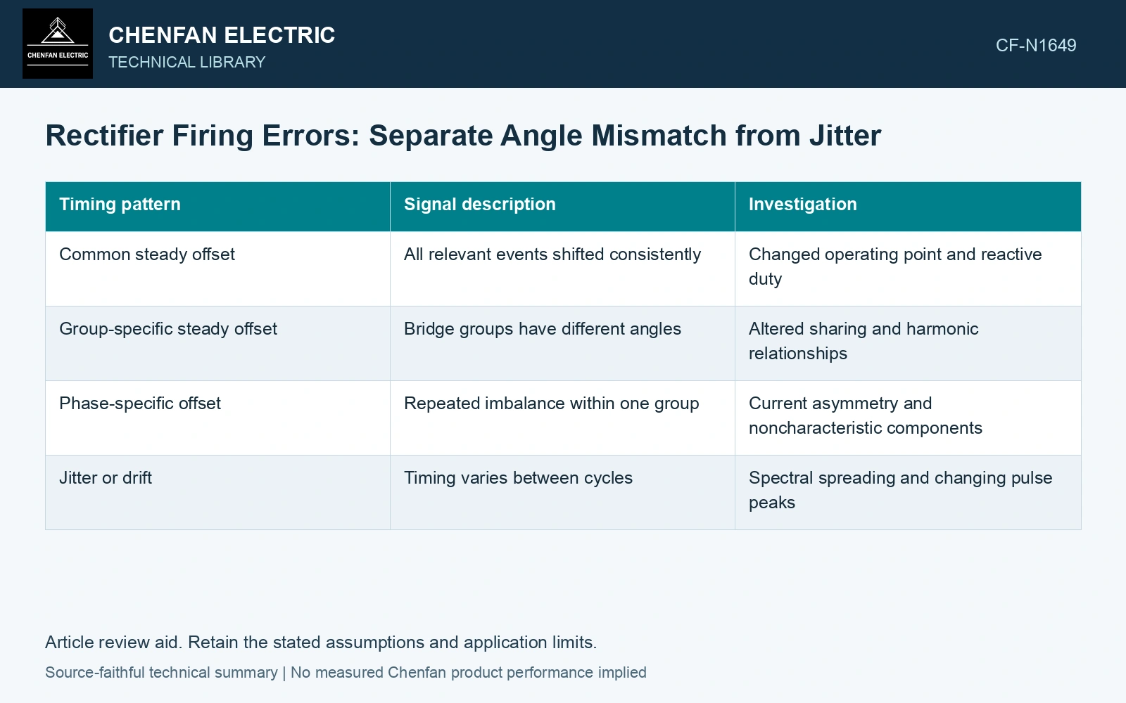
Classify the timing variation
| Timing pattern | Signal description | Investigation |
|---|---|---|
| Common steady offset | All relevant events shifted consistently | Changed operating point and reactive duty |
| Group-specific steady offset | Bridge groups have different angles | Altered sharing and harmonic relationships |
| Phase-specific offset | Repeated imbalance within one group | Current asymmetry and noncharacteristic components |
| Jitter or drift | Timing varies between cycles | Spectral spreading and changing pulse peaks |
A time error Δt corresponds to electrical angle error Δα = ωΔt, in radians. At higher frequency, the same time error represents a larger angle.
For a small ideal shift of a smooth waveform, i(t − Δt) is approximately i(t) − Δt di/dt. This illustrates sensitivity near fast changes. Rectifier conduction boundaries are not always smooth, so actual state changes need a switching model or measured records.
Compare current symmetry directly
Check phase-specific averages, positive and negative conduction areas, peak currents and harmonics. A phase-angle statistic alone cannot show whether the current waveform became asymmetric.
Investigate possible magnetic bias using the winding and voltage relationships. A nonzero current component does not automatically establish a core flux offset; excitation voltage, ampere-turn balance and the control response matter. Preserve voltage-integral evidence where that is part of the analysis.
Compare timing errors on an electrical-angle basis
Assume a 20 µs timing shift. It corresponds to 360 × 50 × 20 × 10⁻⁶ = 0.360° at 50 Hz and 0.432° at 60 Hz, a 20% increase. At 50 Hz, an assumed 10 µs channel timing uncertainty corresponds to 0.180°, half the shift being diagnosed. Verify the acquisition clock and distinguish a repeated offset from cycle-to-cycle spread before changing the firing strategy. Derive winding-current consequences from actual conduction rather than treating these angle values as a current or flux limit.
Use the spectrum suited to the error
For a repeatable steady mismatch, a periodic harmonic description may be appropriate. For jitter, compare time distributions and spectral bands or side components rather than forcing every change into integer harmonic bins.
Check measurement timing and sensor bandwidth. Acquisition jitter or channel delay can resemble controller spread. Validate the common clock before interpreting a small timing difference.
Compare the resulting winding RMS, peaks and spectral duty with the qualified design envelope. If the converter’s timing strategy changes, nominal DC output alone does not establish unchanged transformer loading.
The diagnosis should identify the timing pattern, the actual conduction consequence and the affected winding quantity. That chain is more actionable than labeling every extra harmonic a firing-angle problem or every asymmetrical pulse a saturated core.
Retain an explicit measurement model and input uncertainties when comparing measured and calculated duty [2].
References
- IEC, IEC 61378-1:2011, Converter transformers – Part 1: Transformers for industrial applications.
- JCGM, JCGM 100:2008, Evaluation of measurement data — Guide to the expression of uncertainty in measurement, 2008.