

“Neutral tap” and “line-end tap” describe locations, but they do not fully describe regulation. A tap can change the turns across the energized terminal, the turns supplying the controlled terminal, or an auxiliary injected voltage. Compare complete connection diagrams before comparing switch duty.
For an ideal main winding with common turns NC and series turns NS, the terminal ratio is VH/VL = (NC + NS)/NC. Identify which of those quantities changes at each tap, and which terminal voltage is held fixed.
Follow the turns and volts per turn
If VH is fixed and the energized total turns change, volts per turn changes as VH/(NC + NS). At fixed frequency and waveform, that also changes the main magnetic excitation under the ideal induced-voltage approximation.
If a regulating arrangement changes the controlled voltage while keeping the main energized turns unchanged, the magnetic consequence can differ. Auxiliary or side-limb arrangements cannot be represented reliably by moving a tap symbol on this simple diagram.
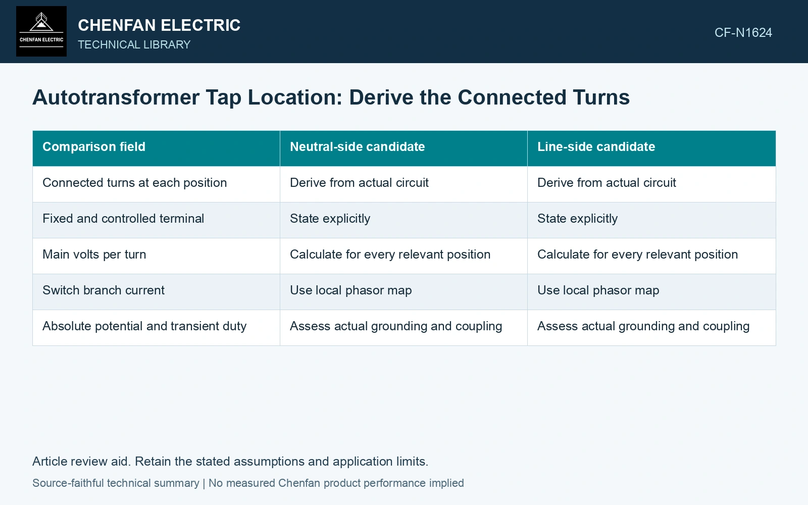
| Comparison field | Neutral-side candidate | Line-side candidate |
|---|---|---|
| Connected turns at each position | Derive from actual circuit | Derive from actual circuit |
| Fixed and controlled terminal | State explicitly | State explicitly |
| Main volts per turn | Calculate for every relevant position | Calculate for every relevant position |
| Switch branch current | Use local phasor map | Use local phasor map |
| Absolute potential and transient duty | Assess actual grounding and coupling | Assess actual grounding and coupling |
Do not assign switch current from the nearest terminal nameplate. A neutral-side branch can carry a current determined by common-section balance or an auxiliary path. The actual regulating circuit controls it.
Separate dielectric and magnetic effects
A branch located near neutral may have a lower steady absolute potential under one grounding condition. Its transient and fault duties still need assessment. Neutral displacement and local coupling can change that potential. Keep connection, tapping and network assumptions explicit in the application assessment [1].
Likewise, a line-side regulator may have a high absolute potential while the voltage across each selected section is relatively small. Both common-mode and differential duties belong in the comparison. Assess the relevant measured quantities with a defined measurement model and propagated uncertainty [2].
Calculate the internal-current map at limiting tap positions and simultaneous port loads. Regulation that preserves the terminal ratio at one operating point may still redistribute winding currents or leakage fields.
Use a topology-specific evidence record
Tabulate connected turns, terminal ratios, main excitation and switch duty together. Keep the signs and winding polarities with the table. This exposes discrepancies that a range label such as “±10% regulation” cannot explain.
The decision should follow the actual regulating function, insulation and current duty. A location label can start the discussion, but it cannot establish that two arrangements have equivalent magnetic behavior or that one switch inherits the other’s rating. Record rated quantities and test conditions on the general power-transformer basis of IEC 60076-1 [3].
Separate a changing common span from a changing series span
Assume 50 Hz, VH = 100 kV RMS and initial turns NC = 800, NS = 200. Initial VL is 80.0 kV and excitation is 100 V RMS per turn. Adding 20 common turns gives VL = 100×820/1,020 = 80.392 kV and 98.039 V per turn. Adding the same 20 turns to the series span instead gives 78.431 kV at L, with the same 98.039 V per turn. The low-port changes have opposite signs. Select switch duty and control logic from the actual connected span, not from an equal turn increment or a tap-location name.
References
- IEC, IEC 60076-8:1997, Power transformers – Part 8: Application guide, 1997, official public scope.
- JCGM, JCGM 100:2008, Evaluation of measurement data — Guide to the expression of uncertainty in measurement, 2008.
- IEC, IEC 60076-1:2011, Power transformers – Part 1: General.