

An impedance quoted on through-power base and one quoted on a winding-duty base can differ substantially while representing the same physical test result. The comparison is meaningful only when the voltage reference and terminal pair are also defined.
For a specified terminal reference, base impedance is Zbase = Vbase²/Sbase using consistent single-phase quantities, or line-to-line voltage and total three-phase power for a balanced three-phase base. Physical referred impedance is Zohm = zpu Zbase.
Preserve the terminal reference
For old and new bases referring to the same port, znew = zold(Snew/Sold)(Vold/Vnew)². Resistive and reactive components follow the same base conversion. A change of physical terminal referral is a separate operation.
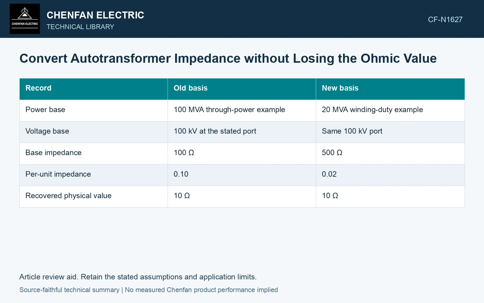
Consider an illustrative balanced three-phase impedance of 0.10 per unit on 100 MVA and 100 kV line-to-line. Zbase is 100 ohms, so the referred impedance is 10 ohms. On a 20 MVA base at the same 100 kV, Zbase is 500 ohms and the value becomes 0.02 per unit. Both return 10 ohms.
| Record | Old basis | New basis |
|---|---|---|
| Power base | 100 MVA through-power example | 20 MVA winding-duty example |
| Voltage base | 100 kV at the stated port | Same 100 kV port |
| Base impedance | 100 Ω | 500 Ω |
| Per-unit impedance | 0.10 | 0.02 |
| Recovered physical value | 10 Ω | 10 Ω |
The 20 MVA value illustrates a transformed-power basis for an ideal ratio example. It does not establish how a manufacturer’s two-winding equivalent defines its own voltage reference. All numerical inputs and limits in the illustrative cases are assumptions unless a catalogue or standard source is explicitly identified.
A section-voltage base is another change
If the new basis uses the series-section voltage rather than the high terminal voltage, the voltage factor must also be applied. Do not change the power base alone and then label the result a series-winding impedance.
Likewise, a measured high-to-low short-circuit impedance and a parameter in an internal equivalent circuit may not be the same physical quantity. Their relationship depends on the connection and how current flows through the sections. Base arithmetic cannot replace that topology derivation.
Close the comparison in ohms
For each reported number, recover its physical referred value using the declared voltage and power bases. Confirm the tap position, frequency and test connection. If the values still disagree, investigate measurement definition or equivalent-circuit mapping rather than applying another unexplained scale factor. Record rated quantities and test conditions on the general power-transformer basis of IEC 60076-1 [1].
Keep the converted complex impedance with its base information in dispatch and fault studies. A percentage without that information is incomplete. The ohmic closure is a simple way to detect a basis mismatch before it becomes a false difference in calculated fault current or winding duty. Keep connection, tapping and network assumptions explicit in the application assessment [2].
Recover the ohmic value after a section-base change
The numerical bases above are assumptions for a balanced 50 Hz three-phase comparison. Keeping the same high-port referral, 0.10 pu on 100 MVA and 100 kV gives 10 Ω. If a reporting base instead uses 20 MVA and 20 kV while deliberately retaining that same high-port-referred 10 Ω parameter, the base impedance is 20 Ω and the value is 0.50 pu. It still recovers 10 Ω. This reporting exercise does not refer the impedance through an ideal transformer to a physical series-section port. Establish that circuit transformation separately before calling the parameter a section impedance. Assess the relevant measured quantities with a defined measurement model and propagated uncertainty [3].
References
- IEC, IEC 60076-1:2011, Power transformers – Part 1: General.
- IEC, IEC 60076-8:1997, Power transformers – Part 8: Application guide, 1997, official public scope.
- JCGM, JCGM 100:2008, Evaluation of measurement data — Guide to the expression of uncertainty in measurement, 2008.