

A tap schedule can have equal turn increments while its terminal ratios change by unequal amounts. This is a consequence of the connection function, not automatically a manufacturing error.
Consider an illustrative ideal arrangement in which series turns NS remain fixed and selected common turns NC change. The ratio r = VH/VL = 1 + NS/NC. This example defines the algebra only; it is not a field reconnection instruction.
Calculate the actual finite steps
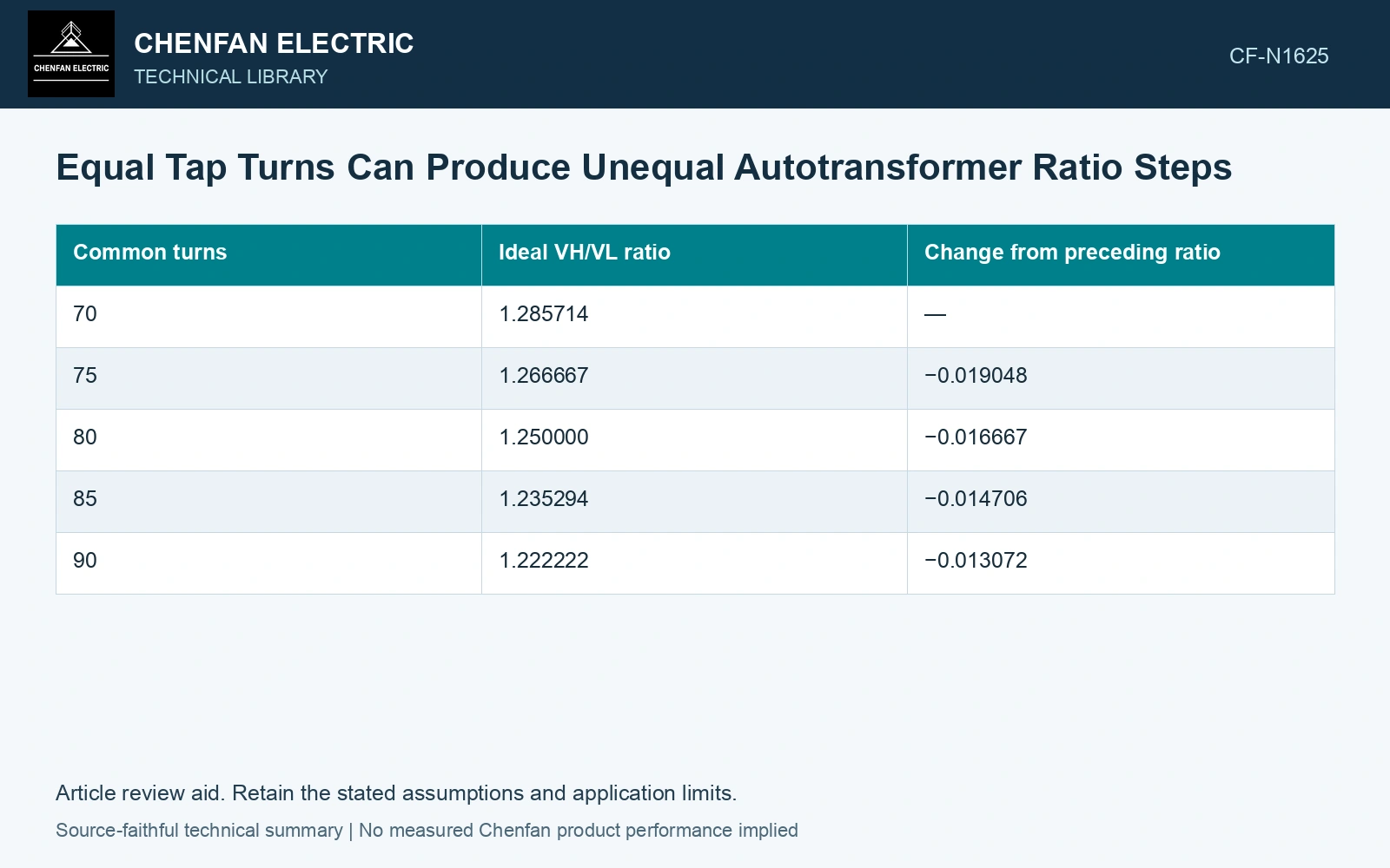
With NS = 20 turns and NC selected in equal five-turn increments, the ratio behaves as follows.
| Common turns | Ideal VH/VL ratio | Change from preceding ratio |
|---|---|---|
| 70 | 1.285714 | — |
| 75 | 1.266667 | −0.019048 |
| 80 | 1.250000 | −0.016667 |
| 85 | 1.235294 | −0.014706 |
| 90 | 1.222222 | −0.013072 |
Ratios and differences are rounded separately to six decimal places.
The ratios decrease, but the absolute step shrinks as NC increases. The local derivative dr/dNC = −NS/NC² explains that sensitivity. For a finite turn increment ΔN, the exact difference is −NSΔN/[NC(NC + ΔN)].
Keep the definition of “step” explicit. An absolute ratio difference, a percentage relative to nominal ratio and a percentage relative to the preceding tap are different quantities.
Fixed source voltage changes the reported result
If VH is held fixed, VL = VH NC/(NC + NS). Its derivative is VHNS/(NC + NS)². Equal NC increments therefore also produce unequal low-terminal voltage increments in this example. All numerical inputs and limits in the illustrative cases are assumptions unless a catalogue or standard source is explicitly identified.
If the regulated terminal is held fixed by control, the required source relationship and magnetic excitation must be evaluated differently. Do not combine a ratio table derived under one fixed-voltage condition with flux conclusions derived under another.
Other connections can place the variable turns in the numerator, in an injected voltage or in both effective winding quantities. Derive their function from the diagram rather than assuming the table above applies to all autotransformers.
Check the schedule at its ends
Calculate each actual position, particularly where sensitivity is greatest. Compare the intended ratio, connected turns and expected measured terminal relationship. Include phase relationship if the regulating topology changes it.
A measured nonuniform ratio sequence should first be compared with the topology’s expected finite differences. It may be correct. A departure from that calculated sequence can then justify investigating selected turns, connection or measurement convention.
Use sufficient numerical precision to compare the schedule, but do not imply a measurement accuracy from the displayed digits. The practical result is a tap table with a defined basis and a predictable sensitivity, allowing a buyer or test engineer to distinguish intentional nonlinear steps from an actual connection discrepancy.
Turn the ratio schedule into a voltage acceptance check
All table turns are normalized assumptions. At an assumed fixed 100 kV RMS source and 50 Hz, the first two low-terminal voltages are 100×70/90 = 77.778 kV and 100×75/95 = 78.947 kV, a 1.170 kV increment. The last step, from 85 to 90 common turns, changes voltage from 80.952 to 81.818 kV, only 0.866 kV. The first increment is 35.1% larger. Use the nonlinear schedule when defining the expected ratio-test values; an equal measured voltage step would be inconsistent with this particular connection [1]. Record rated quantities and test conditions on the general power-transformer basis of IEC 60076-1 [1]. Assess the relevant measured quantities with a defined measurement model and propagated uncertainty [2]. Keep connection, tapping and network assumptions explicit in the application assessment [3].
References
- IEC, IEC 60076-1:2011, Power transformers – Part 1: General.
- JCGM, JCGM 100:2008, Evaluation of measurement data — Guide to the expression of uncertainty in measurement, 2008.
- IEC, IEC 60076-8:1997, Power transformers – Part 8: Application guide, 1997, official public scope.