

A clamp force applied to a shell-form assembly reaches the coil groups through a network of contact surfaces and supports. If an unintended stiff path bridges part of the stack, some load can bypass the groups that need compression.
Draw the load path from the applied restraint to its reaction. Include each pancake group, insulating support and structural contact. Identify which components are in series and which create parallel routes.
Use simple mechanics to expose bypasses
In an ideal series chain without intermediate external loads, the same force passes through every element, while displacement depends on each compliance. In parallel linear paths with a common displacement δ, path i carries Fi = kiδ. A stiffer path carries more load.
These relations are screening tools. Actual contacts can seat sequentially, open, slip or change stiffness. A gap in one path means it may carry no force until the gap closes.
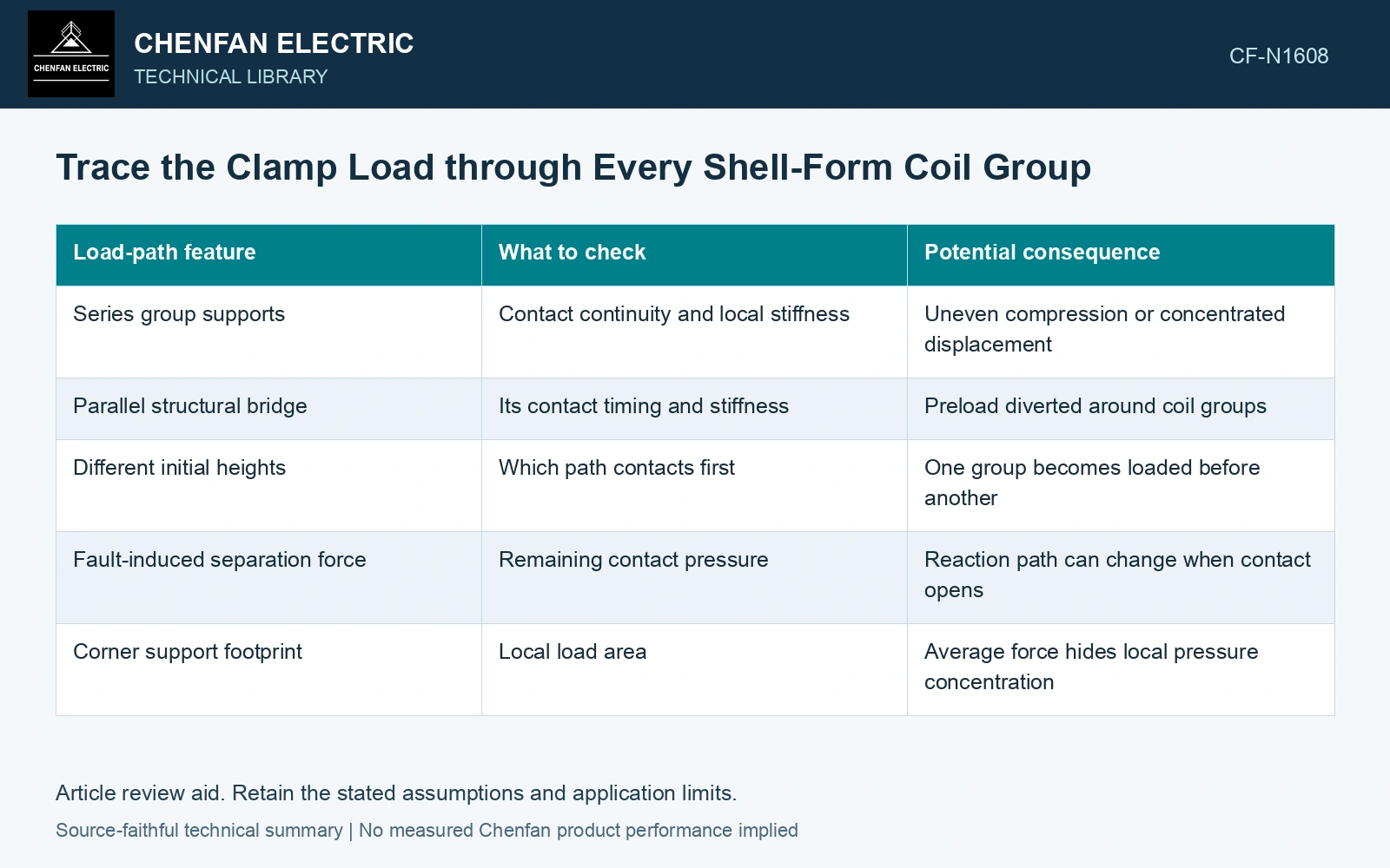
| Load-path feature | What to check | Potential consequence |
|---|---|---|
| Series group supports | Contact continuity and local stiffness | Uneven compression or concentrated displacement |
| Parallel structural bridge | Its contact timing and stiffness | Preload diverted around coil groups |
| Different initial heights | Which path contacts first | One group becomes loaded before another |
| Fault-induced separation force | Remaining contact pressure | Reaction path can change when contact opens |
| Corner support footprint | Local load area | Average force hides local pressure concentration |
Separate assembly preload from additional duty
Calculate or measure the preload state first. Then apply the defined electromagnetic load case to that state. Adding a fault-force magnitude to a total clamp-force magnitude without direction and contact information does not determine local pressure.
Track group forces and moments. Opposing loads can cancel at the complete assembly while increasing compression at one interface and reducing it at another. Check the interface that unloads, not only the largest compressive resultant.
If a contact opens, reassess the structural model. A linear spring that carries tension may represent a restraint that the real insulation support does not possess. The next physical reaction path may be elsewhere in the assembly.
Verify the paths that dominate the decision
Use accessible displacement, strain or pressure-related observations within approved methods to challenge the predicted load distribution. Instrument the relevant paths rather than measuring only the externally applied force. Assess the relevant measured quantities with a defined measurement model and propagated uncertainty [1].
Compare loading and unloading where seating history matters. A later stiff response can follow permanent settling, so the initial assembly state and stabilized state should remain distinct.
The result should identify the intended force route, any bypasses and the interfaces whose pressure can become limiting. That guides changes to support geometry or assembly control. Increasing the total clamp load without tracing its destination can overload an unintended bridge while leaving the underloaded coil group largely unchanged.
Calculate the load lost through a parallel bridge
Assume two engaged linear paths share a total 100 kN preload: the intended coil path has stiffness 20 kN/mm and an unintended bridge has 80 kN/mm. Common displacement is 100/(20 + 80) = 1.0 mm. The coil receives only 20 kN; the bridge takes 80 kN. Removing that bridge in a qualified redesign would put the same 100 kN through the coil path, five times its previous load, with a different displacement. Recalculate contact and insulation pressure before changing the preload. Increasing total force without tracing the bridge does not correct the intended load distribution. Record rated quantities and test conditions on the general power-transformer basis of IEC 60076-1 [2].
References
- JCGM, JCGM 100:2008, Evaluation of measurement data — Guide to the expression of uncertainty in measurement, 2008.
- IEC, IEC 60076-1:2011, Power transformers – Part 1: General.