

A barrier between shell-form coil groups may separate electrical potentials, carry mechanical load and guide insulating liquid. Those functions share a physical part but require different evidence. A dielectric clearance check does not establish the intended oil flow, and a clear passage does not establish dielectric capability.
Draw the two interfaces on the same assembled geometry. Identify the conductive groups and their voltage relationship, then identify the inlet, outlet and alternative liquid routes around the barrier.
Review the electrical boundary
Use the actual voltage duties, including relevant transient conditions, rather than assigning only the terminal RMS voltage to every intergroup space. Specify barrier overlap, edge geometry and oil gaps. Their arrangement determines the field problem.
Use qualification evidence for the actual pressboard, liquid, geometry and manufacturing process. A barrier layout needs its own electrical and hydraulic assessment.
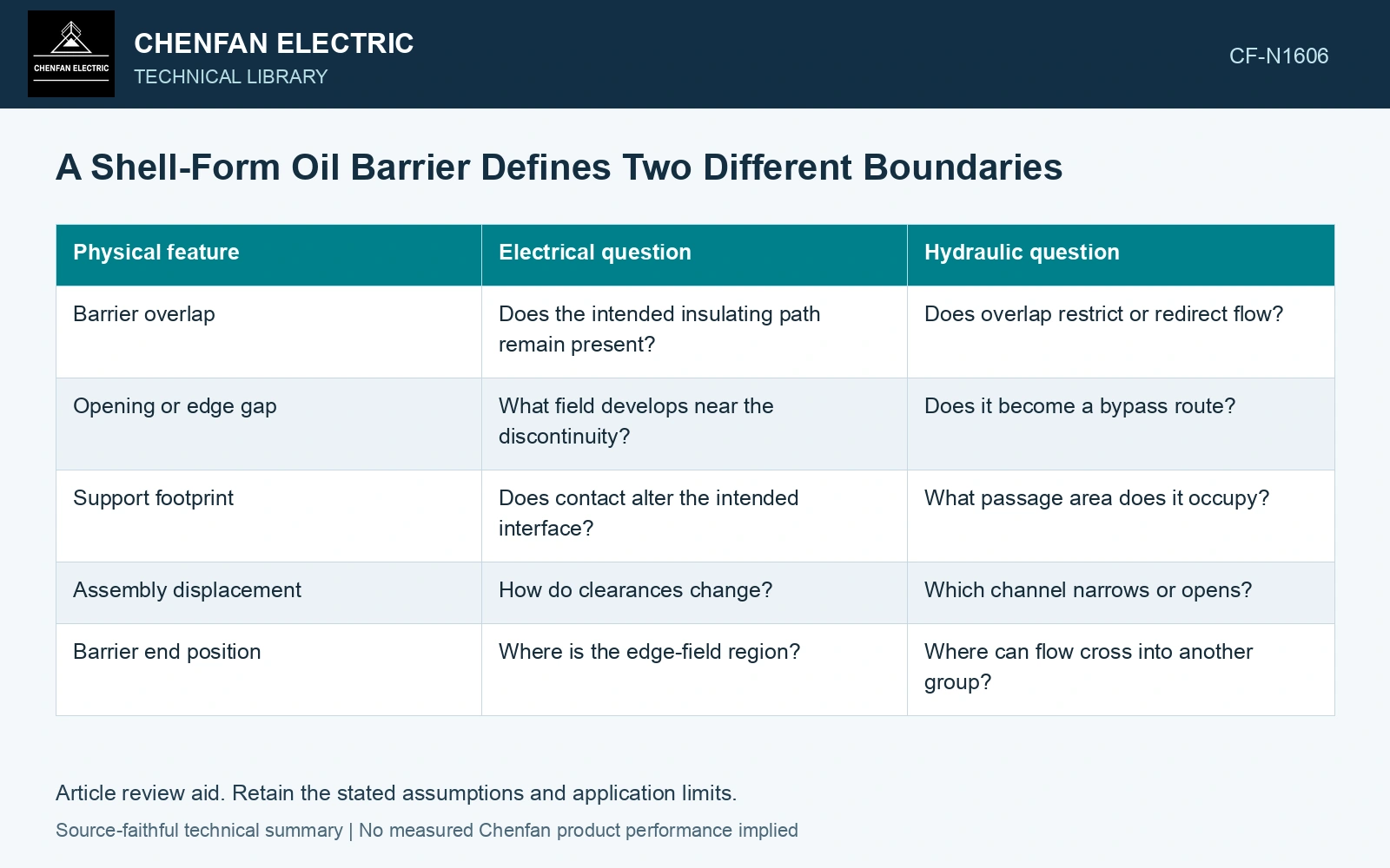
| Physical feature | Electrical question | Hydraulic question |
|---|---|---|
| Barrier overlap | Does the intended insulating path remain present? | Does overlap restrict or redirect flow? |
| Opening or edge gap | What field develops near the discontinuity? | Does it become a bypass route? |
| Support footprint | Does contact alter the intended interface? | What passage area does it occupy? |
| Assembly displacement | How do clearances change? | Which channel narrows or opens? |
| Barrier end position | Where is the edge-field region? | Where can flow cross into another group? |
Follow parallel flow paths
For an idealized hydraulic network, parallel branches share a pressure difference but not necessarily equal flow. Their resistances and temperature-dependent liquid properties determine the distribution. A short corner bypass can therefore carry significant flow while the intended intergroup channel receives less.
Map the routes in the actual assembled state. Include openings created by tolerances or local barrier bow. A nominal section drawing can omit a three-dimensional connection around an edge.
If a simplified resistance model is used, state its geometry and flow assumptions. Narrow rectangular channels, turns and entrance regions may not follow one common relation. Use appropriate validation instead of assigning every branch resistance from length alone.
Check changes jointly
When modifying a barrier to improve one function, reassess the other. Enlarging an opening may increase flow while changing the electrical interface. Extending overlap may change field distribution while restricting a cooling route.
Compare local flow and loss distribution before interpreting temperatures. A hotter group can result from higher loss, reduced flow or both. The barrier assessment should identify the mechanism rather than treating temperature as a direct measure of insulation geometry. Assess the relevant measured quantities with a defined measurement model and propagated uncertainty [1].
Overlay the critical voltage regions and restricted cooling passages on the same barrier geometry. Reassess both after moving a barrier; separate electrical and thermal models cannot resolve the design if they describe different positions. Record rated quantities and test conditions on the general power-transformer basis of IEC 60076-1 [2].
Compare a desired cooling channel with a corner bypass
Assume a fixed pressure difference of 100 Pa, a linear hydraulic resistance of 2.0×10⁸ Pa·s/m³ in the intended channel and 0.50×10⁸ Pa·s/m³ in a corner bypass. Their flows are 0.50 and 2.00 mL/s; only 20% of the combined flow reaches the intended channel. If an approved barrier change doubles bypass resistance, that flow becomes 1.00 mL/s while intended flow remains 0.50 mL/s under this fixed-pressure assumption. Its share rises to 33.3%, but its absolute flow does not rise. Reassess the pump or natural-circulation network and the changed dielectric interface before claiming better local cooling.
References
- JCGM, JCGM 100:2008, Evaluation of measurement data — Guide to the expression of uncertainty in measurement, 2008.
- IEC, IEC 60076-1:2011, Power transformers – Part 1: General.