

A straight cross-section of a coil box can miss the geometry where its sides turn a corner. Curvature, folded insulation, overlaps and conductor transitions change the local field. A two-dimensional result from the long side should not automatically be assigned to that region.
Begin with the manufactured corner rather than an ideal right angle. Record the actual radii, layer termination, overlap and nearby conductive parts. Include plausible assembly movement when it changes a critical gap.
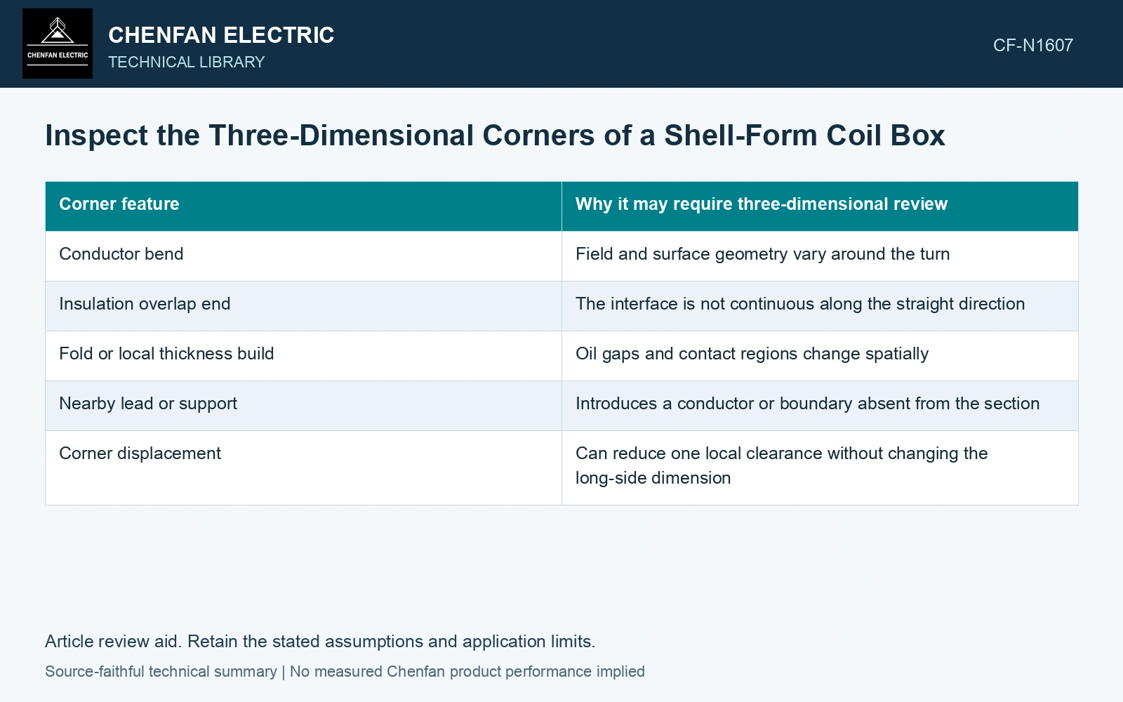
Identify what the straight section omits
| Corner feature | Why it may require three-dimensional review |
|---|---|
| Conductor bend | Field and surface geometry vary around the turn |
| Insulation overlap end | The interface is not continuous along the straight direction |
| Fold or local thickness build | Oil gaps and contact regions change spatially |
| Nearby lead or support | Introduces a conductor or boundary absent from the section |
| Corner displacement | Can reduce one local clearance without changing the long-side dimension |
Compare the straight-region field with the corner model under the same voltage and material assumptions. This isolates the geometric effect. Changing excitation or permittivity at the same time makes the difference difficult to interpret.
Resolve physical edges, not mathematical artifacts
An ideal zero-radius conductor corner can produce a field peak sensitive to mesh refinement. Where the real part has a finite radius, model that radius with a defensible tolerance. Where geometry is uncertain, evaluate the relevant bounded alternatives rather than choosing a convenient smooth shape.
Check spatial field distributions and the locations of maxima. A single global maximum can move between different interfaces as geometry changes. Keep the interface identity with the value so that the assessment remains tied to the appropriate dielectric criterion.
Refine the mesh around the physical corner and compare relevant outputs. A visually smooth contour does not establish convergence. Also check whether the modeled contacts and oil gaps match the assembly state; a nonexistent air or oil sliver can create an artificial high-field region.
Connect the analysis to inspection
Select dimensions that the corner study shows to be influential: an overlap position, a local radius or a gap to a lead, for example. Define accessible inspection features and timing. Buried geometry may need verification before closure.
Use test evidence representative of the insulation system and manufacturing process when qualifying the design. Historical parallel-electrode data can inform a research question but cannot validate a different three-dimensional corner directly. Record rated quantities and test conditions on the general power-transformer basis of IEC 60076-1 [1]. Assess the relevant measured quantities with a defined measurement model and propagated uncertainty [2].
If the corner model changes the limiting region, update the controlled geometry and its verification method. Tightening every coil-box dimension is less useful than controlling the feature that the field assessment identifies. The purpose of the three-dimensional review is that specific decision, rather than producing a larger model of an unchanged straight-section assumption.
Keep a dimensional perturbation with the field comparison
Assume a screening 20 kV RMS difference at 50 Hz across a locally uniform 5.0 mm oil gap. Average field is V/d = 4.0 kV/mm. A corner displacement reducing the actual gap to 4.5 mm raises this average to 4.444 kV/mm, an 11.1% increase; a curved-edge field maximum may change differently. Carry that displacement into the three-dimensional geometry and refine the physical corner. The calculation selects a gap sensitivity for inspection, not an oil-breakdown limit or a criterion for a different insulation system [1].
References
- IEC, IEC 60076-1:2011, Power transformers – Part 1: General.
- JCGM, JCGM 100:2008, Evaluation of measurement data — Guide to the expression of uncertainty in measurement, 2008.