

A shell-form core built around preassembled winding groups must be reviewed as a sequence of motions. The completed geometry can show ample clearance while an intermediate lamination, tool or support has no viable route into position.
Break the sequence into stages using the actual sheet patterns and winding arrangement. At each stage, identify what is already fixed, what remains movable and which insulating surfaces are exposed. Access available early may disappear after the next packet closes the window.
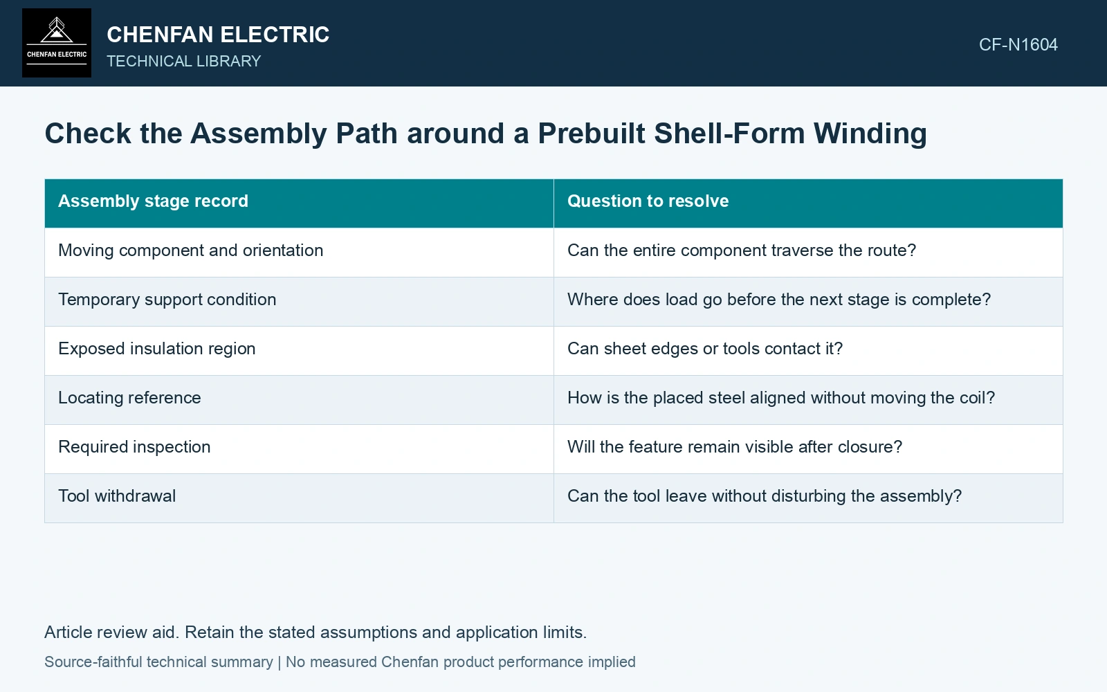
Review the swept space
For each insertion, compare the complete moving envelope with stationary coil boxes, supports and previously placed steel. Include orientation changes and any required tooling. A final-position interference check omits obstacles encountered during travel.
| Assembly stage record | Question to resolve |
|---|---|
| Moving component and orientation | Can the entire component traverse the route? |
| Temporary support condition | Where does load go before the next stage is complete? |
| Exposed insulation region | Can sheet edges or tools contact it? |
| Locating reference | How is the placed steel aligned without moving the coil? |
| Required inspection | Will the feature remain visible after closure? |
| Tool withdrawal | Can the tool leave without disturbing the assembly? |
A temporary spacer or guide also needs a removal path. Leaving that question until closure can force an unplanned movement of steel or insulation.
Protect the coil’s reference and insulation
Use locating features that remain meaningful through the sequence. If the coil box shifts while steel is inserted, later dimensions may be measured from a changed origin. Verify the reference at defined stages rather than assuming it survived every operation.
Identify potential sliding contact with insulating surfaces. Separate geometric access from an approved contact or protection method. A route that is physically possible may still be unsuitable because it scrapes an edge across an insulation corner.
Do not resolve a jam by applying more force without understanding the obstruction. It may indicate a displaced packet, incorrect orientation, temporary support movement or a nominal route that was never feasible.
Test the difficult stage first
Use a representative mock-up or qualified digital motion study for the least accessible operation. Include realistic thickness build and assembly variation. A nominal CAD model with zero uncertainty can make a route appear possible that is unreliable in production.
Define hold points for buried joint inspection before access closes. Associate the readings with layer and stage identity so that a later restacking event does not silently invalidate them.
The assembly review should end with a feasible path for each component, its placement reference and the support state at that moment. That is a more useful readiness criterion than a drawing showing only the final core and coil occupying the same available space.
Check the moving packet against its thickness envelope
For selected GOES stock, the catalogue nominal thickness is 0.23 mm with ±0.02 mm tolerance [1]. Assume a 100-sheet packet must traverse a 24.0 mm opening before rotating into its final location; ignore coating buildup in this steel-only screening check. Nominal build is 23.0 mm, leaving 1.0 mm clearance. The same-sign upper stock tolerance gives 25.0 mm, or 1.0 mm interference. A completed assembly drawing cannot resolve that moving-state conflict. Measure the packet build and tool envelope, or revise the approved sequence before insertion; include coating, burr and handling allowances in the final review. Keep the measured geometry, its reference state and its uncertainty together when evaluating the fit [2].
The assembly route depends on cut-sheet profile, packet thickness, edge burr, joint registration and temporary support location. Control those dimensions at the stage when the joint remains visible. An insertion force is not a substitute for clearance or proof that an insulation surface has remained undamaged.
References
- Nippon Steel Corporation, Grain-Oriented Electrical Steel Sheets, catalogue D004je_03_202004, 2020, Specifications; Size and Form Tolerances.
- JCGM, JCGM 100:2008, Evaluation of measurement data — Guide to the expression of uncertainty in measurement, 2008.