

“Eight pancakes” does not establish a winding’s electrical turns or local magnetic loading. The pancakes may be connected in series, divided into parallel paths, or assigned to groups with different circuit functions. Physical count is useful for describing construction but insufficient for comparing design duty.
Start from the connection diagram. Give each physical section an identifier, turn count, polarity and current path. Then group sections according to their electrical relationship and their spatial position in the shell-form assembly.
A small connection example
Consider four illustrative pancakes, each with 20 turns. All four connected in series produce an 80-turn winding carrying the same current through every pancake. Two equal parallel branches, each containing two series pancakes, produce a 40-turn winding whose terminal current divides between the branches under the balanced assumption.
The same four physical pancakes therefore describe different terminal windings. Their local ampere-turns also differ because each section carries either the full current or a branch current. All numerical inputs and limits in the illustrative cases are assumptions unless a catalogue or standard source is explicitly identified.
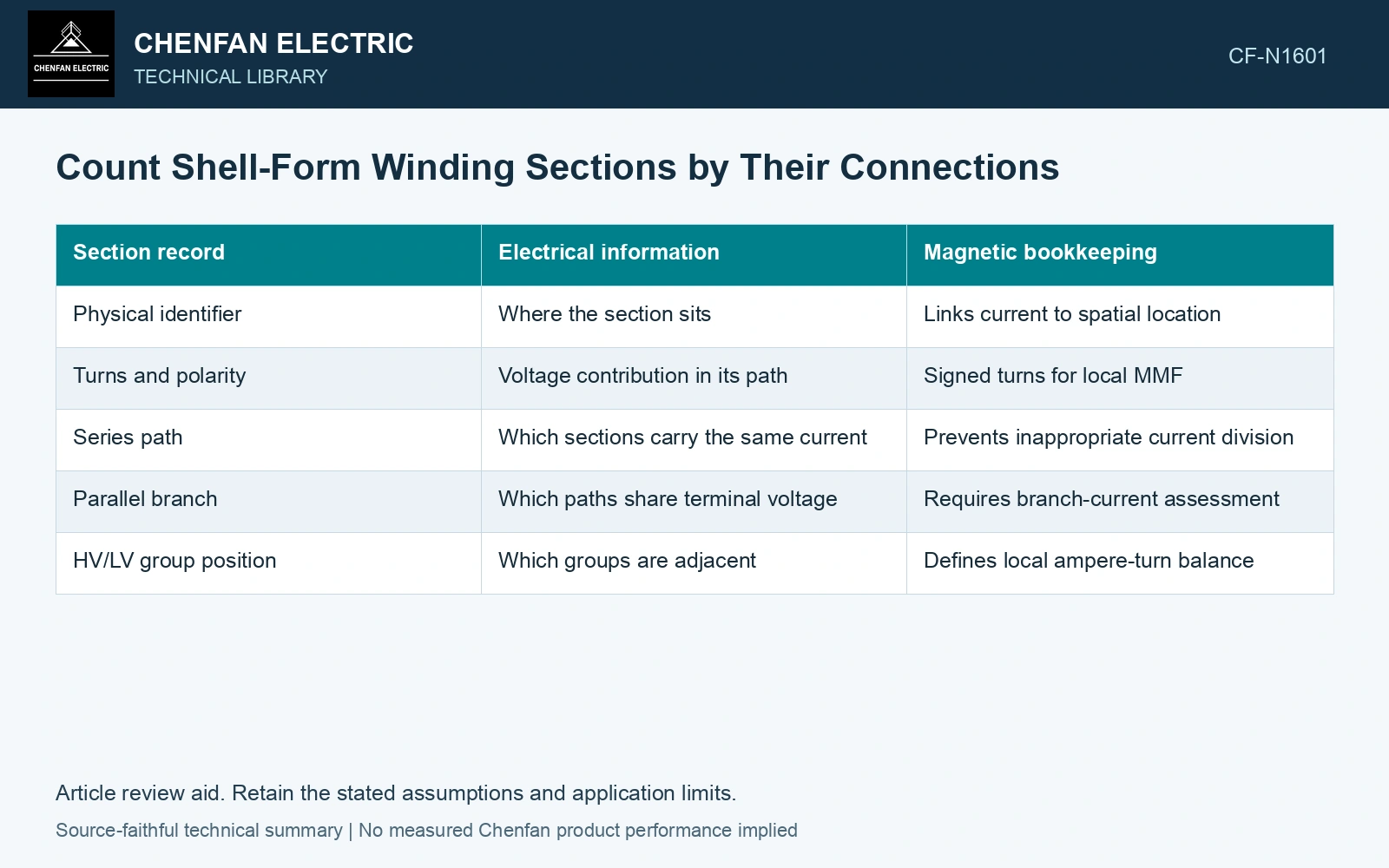
| Section record | Electrical information | Magnetic bookkeeping |
|---|---|---|
| Physical identifier | Where the section sits | Links current to spatial location |
| Turns and polarity | Voltage contribution in its path | Signed turns for local MMF |
| Series path | Which sections carry the same current | Prevents inappropriate current division |
| Parallel branch | Which paths share terminal voltage | Requires branch-current assessment |
| HV/LV group position | Which groups are adjacent | Defines local ampere-turn balance |
For section j, define signed ampere-turns Fj = sjNjIj, with turn count Nj, current Ij in amperes and polarity sign sj. The sign follows a stated orientation; it cannot be inferred from whether a coil is labeled HV or LV alone.
Expand the local balance
Plot or tabulate cumulative signed ampere-turns through the actual group sequence. Under a specified load approximation, the complete winding system may have nearly balanced total ampere-turns while intermediate regions remain unbalanced. Those local regions help define leakage excitation.
Keep magnetizing current and any tertiary or regulating section visible when relevant. A simplified load balance should state what it omits instead of forcing the total to zero by construction.
If parallel branches have different impedance, do not use equal current division automatically. Their individual currents belong in the ledger. Equal turn count is necessary for compatible induced voltage in a simple parallel arrangement, but it does not guarantee equal loaded current. Record rated quantities and test conditions on the general power-transformer basis of IEC 60076-1 [1].
Use the completed map when comparing proposals. Ask whether quoted group counts mean physical pancakes, electrical branches or spatial HV/LV groups. Resolve the terminology before judging force or leakage behavior.
This map is not a detailed field solution. It is the prerequisite that makes one meaningful: every modeled current source has an identified connection, polarity and location. Without it, a visually similar pancake arrangement can conceal a substantially different electrical winding.
Attach current to the section-count comparison
Assume the four 20-turn pancakes above are compared at a terminal current of 100 A RMS and 50 Hz. All-series connection gives 80 effective turns and 20×100 = 2,000 A·turn per pancake. Two identical parallel paths of two series pancakes give 40 effective turns and 50 A per path, or 1,000 A·turn per pancake. The physical count is unchanged, but local ampere-turns halve and terminal volts per turn must be reconciled with the new connection. Reject a comparison that reports only four pancakes; keep turns, current and polarity for each physical section. Assess the relevant measured quantities with a defined measurement model and propagated uncertainty [2].
References
- IEC, IEC 60076-1:2011, Power transformers – Part 1: General.
- JCGM, JCGM 100:2008, Evaluation of measurement data — Guide to the expression of uncertainty in measurement, 2008.