

Shell-form pancake groups experience forces from their currents and leakage fields. The direction and magnitude depend on the actual connection, group arrangement and field distribution. Importing a concentric core-form winding’s radial-force description can assign the wrong mechanical problem.
Identify each group’s current direction and the load case. Use the corresponding field solution, including end regions and neighboring groups. Global ampere-turn balance does not eliminate local leakage or local force.
Calculate loads at the group level
Under a suitable electromagnetic formulation, conductor force density is f = J × B, in newtons per cubic metre when J is in amperes per square metre and B in teslas. Integrate over a defined conductor region to obtain its force vector. The treatment of self-field and equivalent group currents must be consistent with the chosen method.
Keep force components in a coordinate system tied to the pancake. Distinguish motion normal to its face from in-plane loads. A force magnitude without direction cannot select the correct support mechanism.
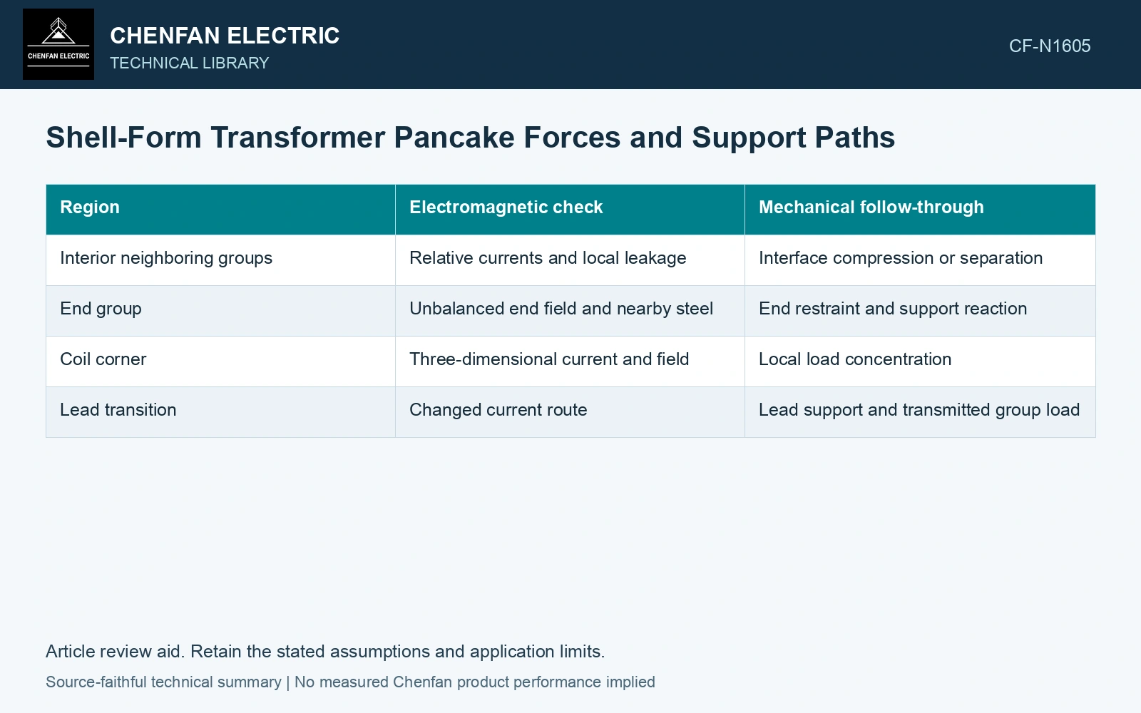
| Region | Electromagnetic check | Mechanical follow-through |
|---|---|---|
| Interior neighboring groups | Relative currents and local leakage | Interface compression or separation |
| End group | Unbalanced end field and nearby steel | End restraint and support reaction |
| Coil corner | Three-dimensional current and field | Local load concentration |
| Lead transition | Changed current route | Lead support and transmitted group load |
Close the reaction balance
Sum group forces and moments, then trace them through insulating supports, clamping members and the relevant structural restraints. A low total force can coexist with large internal opposing loads. Those loads still act through individual contact areas and may change local pressure.
Check whether each interface remains in contact under the additional load. A support that carries compression in the assembly preload may not carry tension when a group tends to separate. If separation occurs, the reaction path can change and invalidate a linear contact assumption.
Use the actual fault current waveforms or the approved equivalent load case. Peak force timing need not coincide with the peak of every current independently. A static peak assessment must state how the combined condition was chosen.
Verify the source and the support model separately
Check field discretization and integrated force balance before transferring loads to mechanics. Then check structural equilibrium, contact state and displacement. A good electrical force calculation cannot compensate for a support model that sends the load through a physically absent restraint.
Compare alternative group arrangements using both local loads and their paths. Partial electromagnetic cancellation can be useful, but it does not establish short-circuit withstand capability by itself. The design decision requires the remaining forces to reach qualified supports without unacceptable movement or insulation loading.
Transfer a directional conductor load to its actual support
Assume a straight conductor segment carrying 10 kA at the instantaneous fault condition, perpendicular to a locally uniform externally produced 0.10 T field over 0.50 m. F = IlB gives 500 N normal to the selected plane. Two equal engaged supports would each react 250 N. If their assumed bearing areas are 100 mm² each, average pressure is 2.5 MPa. Reversing the external field reverses force; it cannot be represented by adding only a positive scalar load. Transfer the vector and moment to the contact model and check separation before comparing with qualified support data. Record rated quantities and test conditions on the general power-transformer basis of IEC 60076-1 [1]. Assess the relevant measured quantities with a defined measurement model and propagated uncertainty [2].
References
- IEC, IEC 60076-1:2011, Power transformers – Part 1: General.
- JCGM, JCGM 100:2008, Evaluation of measurement data — Guide to the expression of uncertainty in measurement, 2008.