

Alternating HV and LV groups can reduce some local ampere-turn imbalances compared with separating all HV groups from all LV groups. The result depends on group turns, currents, spacing and geometry. A greater number of alternations is not a complete design metric.
Compare arrangements that perform the same electrical duty. Keep terminal turns, connection, loading and the relevant insulation conditions consistent. Otherwise a lower calculated leakage result may come from a changed winding rather than from its sequence.
Screen the group sequence
Use signed group ampere-turns to calculate the cumulative balance across the pancake arrangement. This one-dimensional ledger identifies regions where leakage excitation can be large. It is a screening tool; actual leakage paths around rectangular coils are three-dimensional.
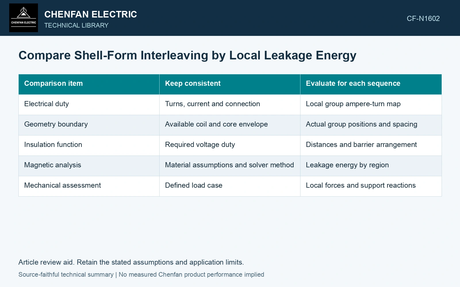
| Comparison item | Keep consistent | Evaluate for each sequence |
|---|---|---|
| Electrical duty | Turns, current and connection | Local group ampere-turn map |
| Geometry boundary | Available coil and core envelope | Actual group positions and spacing |
| Insulation function | Required voltage duty | Distances and barrier arrangement |
| Magnetic analysis | Material assumptions and solver method | Leakage energy by region |
| Mechanical assessment | Defined load case | Local forces and support reactions |
Under linear magnetic assumptions, stored field energy can be written W = ½∫B·H dV, in joules. Partition the leakage-field region consistently between arrangements. Integrating different volumes or including different amounts of main-core energy makes the comparison ambiguous.
Relate energy to an equivalent inductance only for a clearly defined current coordinate and circuit condition. For a single linear coordinate, W = ½LI². A multiwinding system generally requires an inductance matrix and specified currents.
Inspect where the energy moves
A lower total can coexist with a more concentrated local field near a lead, clamp or end group. Report spatial distributions as well as the total. Compare structural-metal exposure and group forces at locations that changed.
Interleaving also changes which voltages appear across neighboring groups. Retain their insulation duty in the assessment. An arrangement that reduces one leakage region may introduce a more demanding dielectric interface or a less accessible cooling passage. Record rated quantities and test conditions on the general power-transformer basis of IEC 60076-1 [1].
Do not assume that a passing impedance calculation proves short-circuit mechanical capability. Force distribution and support paths must be evaluated for the actual fault currents and geometry. Opposing forces can partly balance globally while each group still carries a local load.
Use the comparison to identify a defensible sequence within the full design constraints. The technical argument should show the same electrical function, where leakage energy changes and how the resulting local duties are supported. An alternation count alone cannot make that case.
Rank two sequences using the same simplified gap model
Assume four groups have signed 1,000 A·turn magnitudes at one common current coordinate. Sequence H-H-L-L has cumulative gap MMFs of 1,000, 2,000 and 1,000 A·turn. H-L-H-L gives 1,000, 0 and 1,000 A·turn. For equal linear gaps, energy is proportional to the sum of squared gap MMFs: 6.0×10⁶ versus 2.0×10⁶ (A·turn)², a 66.7% decrease in this screening model. If corresponding assumed field energies are 30 and 10 J at 100 A, equivalent inductances are 6 and 2 mH. Advance the second sequence for full three-dimensional dielectric, thermal and force comparison; the MMF ledger alone cannot qualify it. Assess the relevant measured quantities with a defined measurement model and propagated uncertainty [2].
References
- IEC, IEC 60076-1:2011, Power transformers – Part 1: General.
- JCGM, JCGM 100:2008, Evaluation of measurement data — Guide to the expression of uncertainty in measurement, 2008.