

A cut lamination rarely presents a mathematically sharp apex. Corner finishing, edge rounding and a deliberate drawing allowance can all move the visible endpoint away from the intersection of its straight edges. Measuring that endpoint without reconstructing the reference makes truncation results ambiguous.
First determine what the drawing controls. It may specify a theoretical intersection, an actual corner profile or a permitted material-removal region. Those are different requirements. An intentional finish should not be classified as missing joint material merely because the theoretical lines continue beyond it.
Reconstruct the intersection
Fit each straight edge over a defined region clear of the rounded or truncated corner. Extend the fitted lines to their intersection. Record the included angle and the fit regions because short or irregular edges can make the extrapolated point uncertain.
Then describe the real corner relative to that intersection. Useful quantities include the distance along each edge to the start of truncation and the normal distance from the theoretical apex to the truncating line. A single camera pixel labeled “tip” does not reproduce that definition.
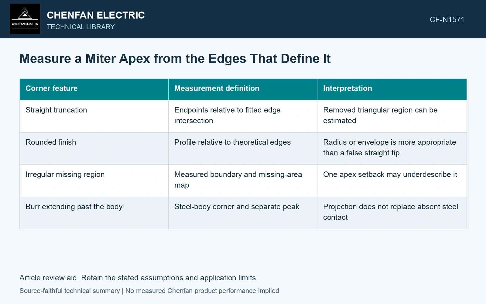
| Corner feature | Measurement definition | Interpretation |
|---|---|---|
| Straight truncation | Endpoints relative to fitted edge intersection | Removed triangular region can be estimated |
| Rounded finish | Profile relative to theoretical edges | Radius or envelope is more appropriate than a false straight tip |
| Irregular missing region | Measured boundary and missing-area map | One apex setback may underdescribe it |
| Burr extending past the body | Steel-body corner and separate peak | Projection does not replace absent steel contact |
For an illustrative symmetric corner with equal edge setback a and included angle φ, the removed triangle has area A = ½a² sin φ. Here a is in millimetres and A is in square millimetres. This relation applies only when the missing region is bounded by the two straight edges and the line joining the setback points.
Evaluate the joint in its assembled position
A missing corner area on an isolated sheet is not automatically the lost magnetic contact area of the complete step-lap joint. Overlap, neighboring layers and assembly position determine how the region participates in the flux path.
Compare the measured corner with the approved assembled joint geometry. Identify whether it creates an additional local separation, falls within an intentional relief, or is covered by the intended layer sequence. Preserve the layer position in the record; identical cut profiles may have different joint roles.
Do not extrapolate a loss increase directly from removed area. Flux redistribution and local saturation require the actual magnetic configuration. The geometric result can identify a departure needing design assessment without claiming an unsupported electrical penalty.
For corrective action, distinguish cutter-generated truncation from a displaced sheet. One requires cut-profile control; the other requires assembly alignment. A clearly defined theoretical apex makes that distinction possible and prevents a corner photograph from becoming an argument about where the measurement began.
Quantify removed steel at the reconstructed apex
The catalogue nominal thickness of 23ZH90 is 0.23 mm [1]. Assume a straight symmetric truncation with equal edge setbacks a = 2.00 mm and included angle 90°. Removed area is ½ × 2.00² × sin 90° = 2.00 mm²; removed steel volume per sheet is 2.00 × 0.23 = 0.460 mm³. An assumed drawing allowance of 1.50 mm² is exceeded by 0.50 mm². If each setback is instead 1.50 mm, area is 1.125 mm², below that allowance before uncertainty [2]. Assess the reconstructed profile against the drawing; neither volume nor missing tip area directly predicts assembled-core loss.
Manufacturing controls. Cutter geometry, feed alignment, blade condition, corner finishing and layer placement control the apex. Measure the underlying straight edges separately from burr peaks so that cut-profile correction is not confused with restacking.
References
- Nippon Steel Corporation, Grain-Oriented Electrical Steel Sheets, catalogue D004je_03_202004, 2020, Specifications; Size and Form Tolerances.
- JCGM, JCGM 100:2008, Evaluation of measurement data — Guide to the expression of uncertainty in measurement, 2008.