

A stepped limb approximates a circular envelope with intentionally different packet widths. A roundness calculation against one ideal circle therefore includes the designed steps. Reporting that total as manufacturing error can make a correct core appear poor.
Start with the nominal stepped profile. Register the measured section to the functional reference specified for that profile. Then compare corresponding regions. The design’s facets and corners are the baseline, not noise to be averaged away.
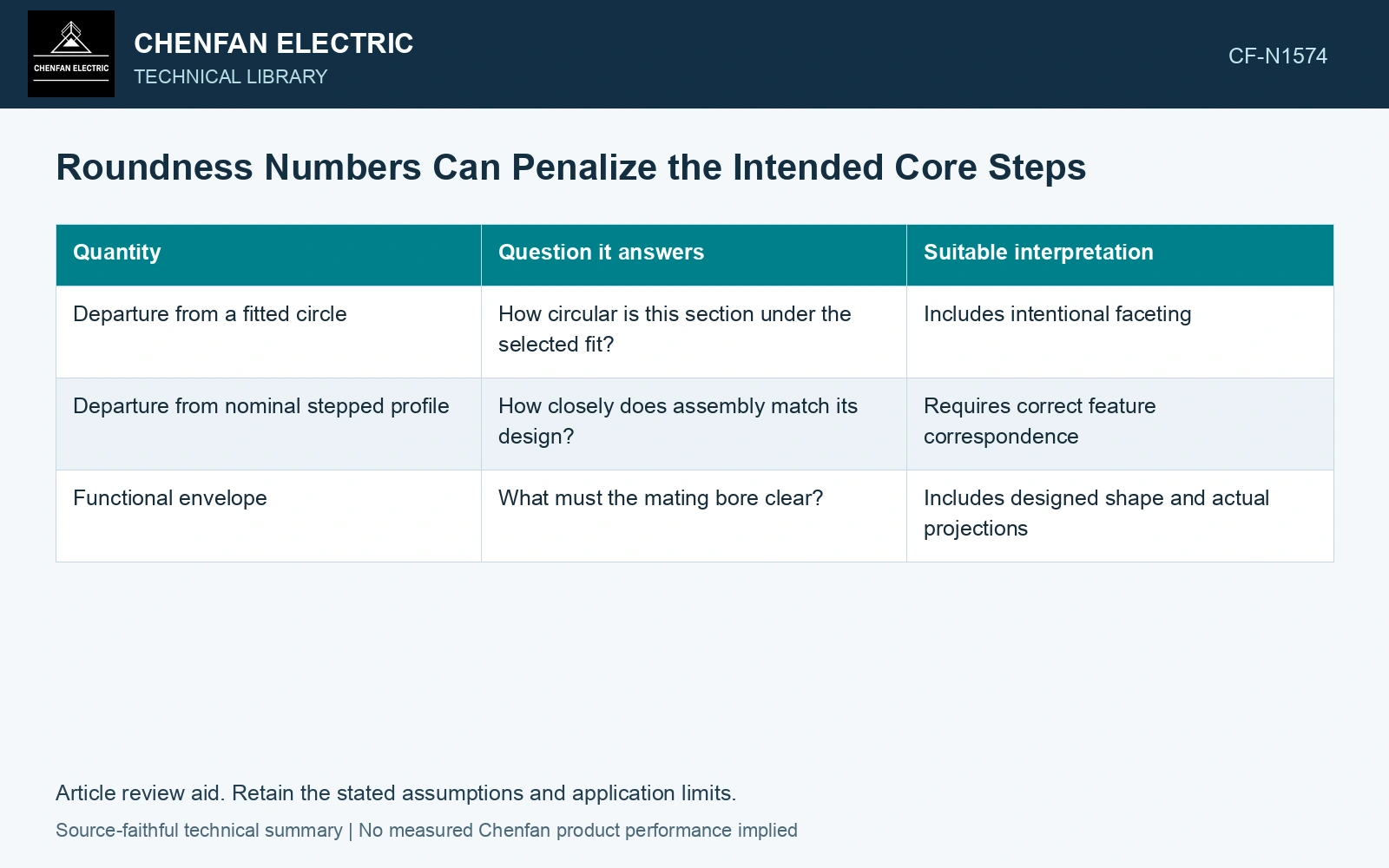
Separate three quantities
| Quantity | Question it answers | Suitable interpretation |
|---|---|---|
| Departure from a fitted circle | How circular is this section under the selected fit? | Includes intentional faceting |
| Departure from nominal stepped profile | How closely does assembly match its design? | Requires correct feature correspondence |
| Functional envelope | What must the mating bore clear? | Includes designed shape and actual projections |
These quantities can all be useful, but they should not share an unlabeled “roundness” value. A core with a large designed facet difference may have small manufacturing residuals. A generally circular section may still have a single harmful projection.
For a profile expressed radially about a common axis, define e(θ) = rmeasured(θ) − rnominal(θ), in millimetres. Positive e indicates outward departure at the same angular position. This comparison assumes the measured and nominal profiles are correctly aligned and each radial direction has a meaningful corresponding boundary.
Keep the angle with the residual. The maximum, minimum and distribution can summarize the data, but the location explains whether the departure is on a broad facet, at a packet transition or on one displaced sheet.
Do not let registration absorb the error
A free best-fit transformation can move the measured profile until its average residual is small. That may be appropriate for comparing cut shape, but it can hide displacement relative to the winding axis. Use the reference required by the assembly function, and report any alignment adjustment made for a separate shape-only comparison.
Likewise, avoid stretching or scaling the nominal model to match the measurement unless the purpose explicitly permits it. Such a fit can conceal a dimensional build error.
Inspect packet transitions with enough spatial coverage to retain local high points. Broad facet averages can be stable while a narrow projecting lamination is lost through filtering. Keep raw data around the largest residual and confirm it with a suitable independent method when it controls the decision.
The result should identify the intended shape, the measured departures and the actual fit consequence. A supplier and OEM can then discuss the same geometry. Requiring a smaller generic roundness number may otherwise drive changes to the designed stepping without improving the winding’s clearance.
Compare the facet residual before fitting a circle
Use a nominal packet of 100 × 0.23 mm 23ZH90 sheets, giving 23.0 mm steel-only build [1]. Assume the approved radial profile has a 100.0 mm corner and a 98.0 mm facet, while the corresponding measured radii are 100.1 and 98.1 mm. The intended radial step is 2.0 mm, but both manufacturing residuals are only +0.1 mm. A circle-based radial range still reads 2.0 mm and does not distinguish design from error. With an assumed 100.5 mm bore radius and fixed shared axis, the limiting clearance is 100.5 − 100.1 = 0.4 mm before uncertainty and assembly allowance [2]. Retain the stepped nominal geometry.
Manufacturing controls. Packet widths, sheet counts, compression and alignment establish the designed facets. Their inspection must preserve corners and local projections; free recentering or smoothing may improve a fit statistic while hiding the surface that controls insertion.
References
- Nippon Steel Corporation, Grain-Oriented Electrical Steel Sheets, catalogue D004je_03_202004, 2020, Specifications; Size and Form Tolerances.
- JCGM, JCGM 100:2008, Evaluation of measurement data — Guide to the expression of uncertainty in measurement, 2008.