

Short answer
Delta-connected loads transformer models must handle loads connected between phases rather than from phase to neutral. A delta load’s branch current flows between two lines, and each line current is the difference of two branch currents. In an illustrative case, a 10 kW resistive load connected between phases a and b of a 400 V system draws 25 A in its branch, and 25 A in lines a and b, with nothing in line c. Mapped onto phase-to-neutral quantities, that load appears as about 4.98 kW on each of phases a and b, with about +2.9 kvar on one and −2.9 kvar on the other, even though the load itself is purely resistive. Models that split delta loads equally onto phases as if they were wye loads misstate phase currents, neutral current and losses. Delta loads should be modelled as line-to-line elements.
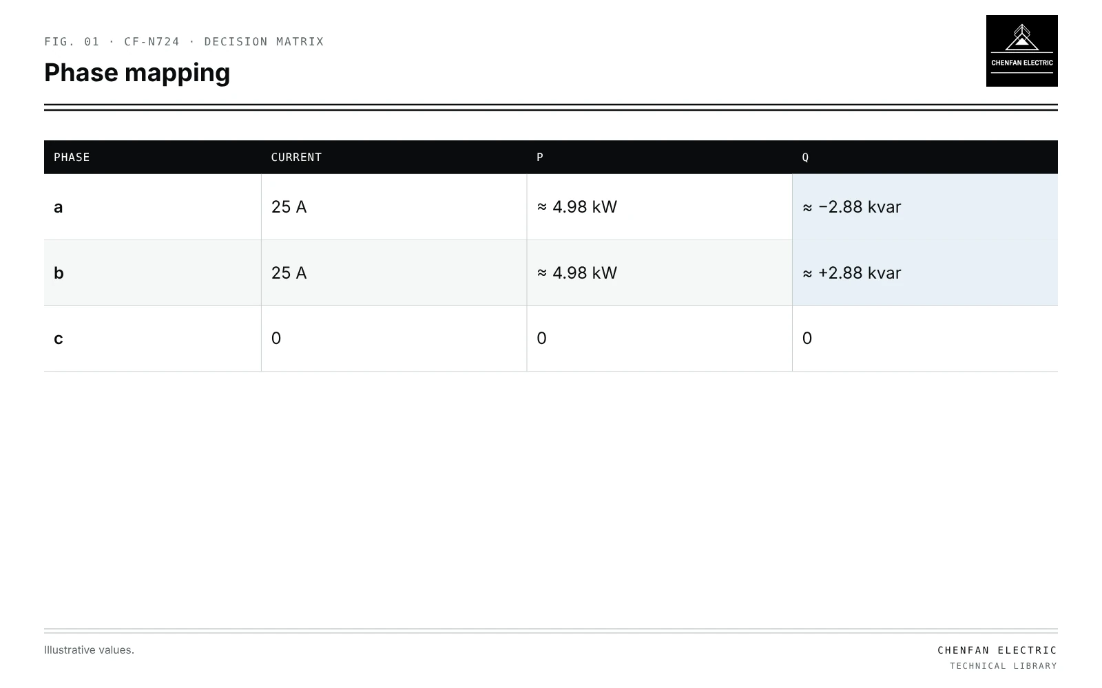
Branch and line currents
| Phase | Current | P | Q |
|---|---|---|---|
| a | 25 A | ≈ 4.98 kW | ≈ −2.88 kvar |
| b | 25 A | ≈ 4.98 kW | ≈ +2.88 kvar |
| c | 0 | 0 | 0 |
I_a = Iab − Ica, I_b = Ibc − Iab, I_c = Ica − Ibc
Delta loads carry no neutral current; their line currents sum to zero.
Single line-to-line load
Illustrative example. 10 kW resistive load between phases a and b; 400 V line-to-line, 230 V phase-to-neutral. Values chosen for demonstration.
Iab = 10,000 / 400 = 25 A, in phase with V_ab (leading V_a by 30°)
I_a = 25∠30° A, I_b = 25∠210° A, I_c = 0
Phase-referenced powers:
S_a = V_a I_a^* = 230 × 25 ∠−30° ≈ 4.98 kW − j2.88 kvar
S_b = V_b I_b^* ≈ 4.98 kW + j2.88 kvar
The reactive parts cancel in total. Each phase appears to carry reactive power; per-phase power factor is 0.87 although the load is resistive.
Errors from wye approximation
| Modelling choice | Effect |
|---|---|
| Split as wye, 5 kW on a and b | Wrong current angles; neutral current appears |
| Split equally on three phases | Phase c carries current it does not have |
| Delta element | Correct line currents and no neutral current |
Wrong representation affects neutral loading, phase voltage drops and transformer phase loading; see unbalanced load flow with an explicit neutral.
Data sources
- Connection type of each load from customer records or field data.
- AMI data for two-phase services, recorded line-to-line or per phase depending on meter.
- Three-phase motors are balanced delta or wye; their connection matters less for line currents, but single-phase line-to-line loads matter.
- Phase mapping in GIS conversions must keep line-to-line labels; see transformer phase mapping in GIS-to-power-flow conversion.
Transformer connection
The transformer secondary connection, for example 120/240 V split-phase or 400/230 V wye, determines which loads are line-to-line. Open-delta and similar banks add further asymmetry. Load allocation from meters must respect this; see calibrating transformer load allocation with AMI data.
What this article does not cover
The choice of delta or star for the transformer high-voltage winding is a separate topic and is not covered here.
Where this reasoning stops. The example is a single resistive load; mixed loads need full phasor modelling.
Practical takeaway
Model line-to-line loads as delta elements, expect phase-referenced powers to show apparent vars, and keep connection data from field records through GIS conversion to the load flow.
Reference framework
- W. H. Kersting, Distribution System Modeling and Analysis (delta-connected loads).