


Transformer Core Engineering Notes · CF-N259
The label “winding temperature” on an instrument does not necessarily mean a sensor is inside the winding. Some indicators produce a thermal image using liquid temperature and a load-related heating or calculation arrangement. Others display a direct sensing location. Procurement and operating documents should state which method is installed and what its indication represents.
Identify the measurement chain
For a thermal-image indicator, document the temperature input, load-related input and the model or compensation arrangement. For a direct system, record the physical sensing location and channel mapping. Do not treat these chains as interchangeable because both displays use degrees Celsius. Their errors, response and failure modes differ, so alarm and cooling-control functions need to be assessed against the actual instrument design.
Connect settings to transformer test evidence
Compensation values should reflect the OEM’s specified winding-temperature relationship and the applicable test basis. A replacement instrument with factory-default settings may not reproduce the previous approved indication. Record the relevant current-transformer ratio, instrument configuration and calibration or functional checks as applicable. Changes to cooling stages or transformer rating should trigger a review of the indication model, not merely a new label on the dial.
Interpret disagreement before changing settings
A thermal-image value and a fibre-optic channel can legitimately differ because they represent different locations or response models. Investigate the operating state, placement and measurement chain before assuming one must be wrong. Never adjust an indicator merely to make two traces coincide without an engineering basis. A comparison is useful when the expected relationship and its uncertainty are defined in advance.
Specify failure behavior and handover records
Clarify how loss of a sensor, load input, auxiliary supply or communication affects the display and its outputs. A frozen plausible value can be harder to recognize than a clear fault indication. The handover package should include final settings, channel descriptions, control functions and test records. The operating team needs to know whether it is seeing a modelled winding quantity or a direct local measurement before using it for decisions.
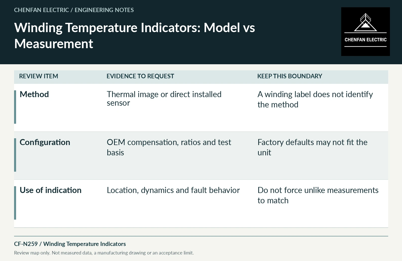
| Review item | Evidence to request | Boundary to preserve |
|---|---|---|
| Method | Thermal image or direct installed sensor | A winding label does not identify the method |
| Configuration | OEM compensation, ratios and test basis | Factory defaults may not fit the unit |
| Use of indication | Location, dynamics and fault behavior | Do not force unlike measurements to match |
References and scope
- IEEE C57.165-2024 — Temperature Monitoring of Liquid-Immersed TransformersPublic standard abstract · Temperature-monitoring methods for liquid-immersed transformers and their measurement/model boundaries.
- IEEE C57.91-2025 — Loading Mineral-Oil-Immersed Transformers and Step-Voltage RegulatorsPublic standard abstract · Mineral-oil loading, thermal duty and loading beyond nameplate; do not transfer the scope automatically to ester or dry-type equipment.