


Transformer Core Engineering Notes · CF-N255
A fibre-optic winding sensor offers a temperature measurement at its installed sensing location. That can be valuable evidence, but the sensor does not automatically find the hottest point in the entire transformer. Sensor selection and placement should be part of the winding design and test plan, with their limitations stated before the resulting readings are used for loading decisions.
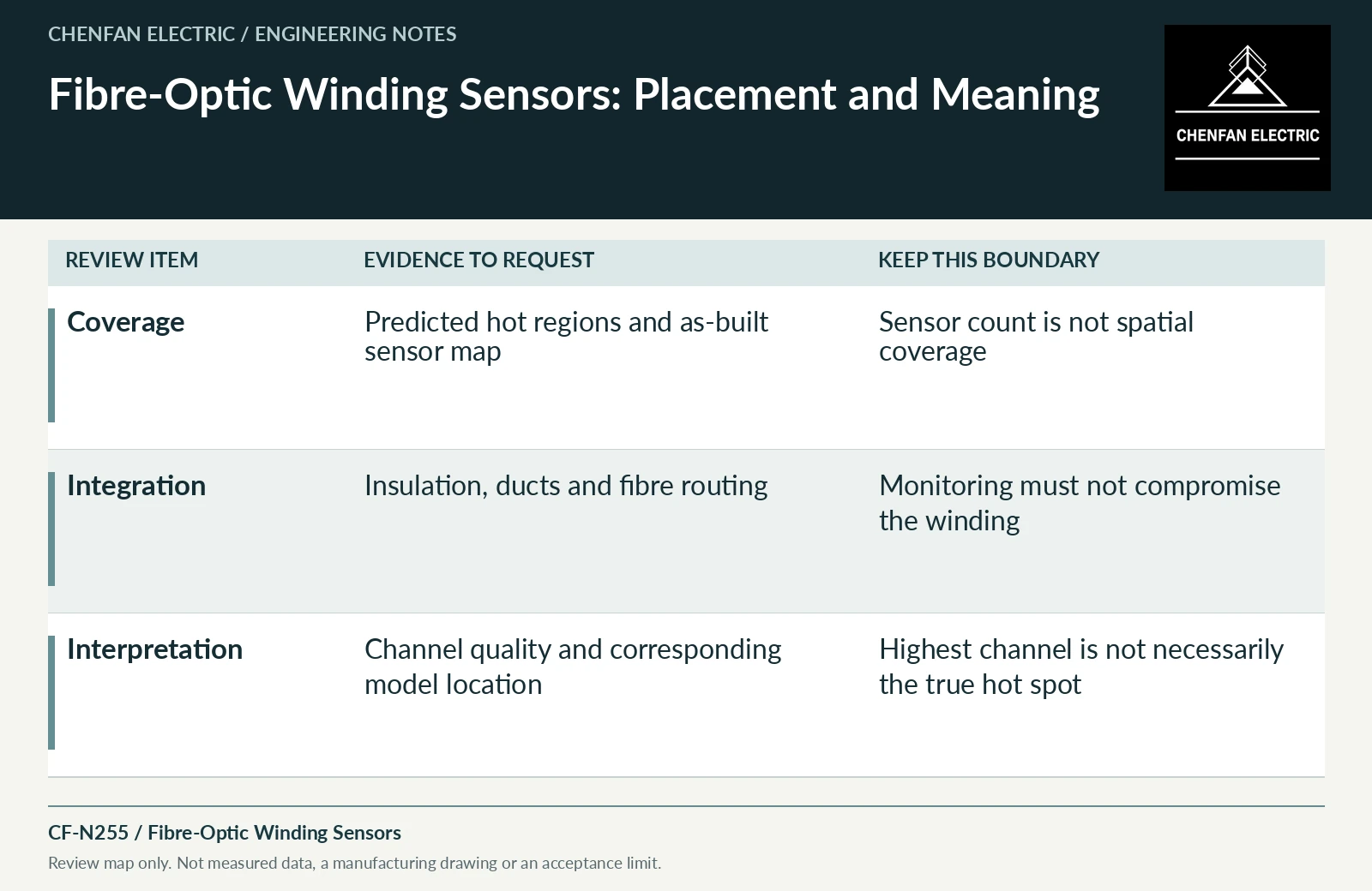
Select locations from the thermal design
Ask how predicted critical regions were identified and whether different windings, tap positions or cooling states move the likely hot spot. The number of sensors alone does not describe coverage. Record the intended location of each sensing tip on an approved drawing and retain the as-built position. A location change made for easier assembly may change the meaning of the measurement even when the sensor specification remains unchanged.
Protect insulation and cooling functions
The sensing assembly and fibre route must be compatible with the dielectric, mechanical and processing requirements of the winding. Review their effect on local insulation, ducts and assembly clearances with the OEM and sensor supplier. Installation must follow the approved design and qualified procedures. A monitoring device should not introduce an unreviewed obstruction or damage-sensitive route in the region it is intended to observe.
Preserve channel identity and measurement quality
The commissioning record should map channels to physical locations and document the measurement system’s applicable checks. An unexplained channel renaming can make a correct reading operationally misleading. Distinguish a failed or unavailable channel from a genuinely low temperature. Review resolution, uncertainty and response characteristics against the purpose of the measurement rather than treating the display’s decimal places as proof of accuracy.
Use readings to test a model, not replace judgment
Compare measurements with predictions for the corresponding locations and operating states. A mismatch can arise from placement, instrumentation, model assumptions or actual thermal behavior; investigate before choosing the most convenient explanation. A measured maximum across installed channels is the maximum of those channels, not necessarily the whole winding. Loading limits should retain the OEM’s assessment of unsensed regions and other limiting components.
| Review item | Evidence to request | Boundary to preserve |
|---|---|---|
| Coverage | Predicted hot regions and as-built sensor map | Sensor count is not spatial coverage |
| Integration | Insulation, ducts and fibre routing | Monitoring must not compromise the winding |
| Interpretation | Channel quality and corresponding model location | Highest channel is not necessarily the true hot spot |
References and scope
- IEEE C57.165-2024 — Temperature Monitoring of Liquid-Immersed TransformersPublic standard abstract · Temperature-monitoring methods for liquid-immersed transformers and their measurement/model boundaries.
- IEC 60076-2:2011 — Temperature rise for liquid-immersed transformersPublic standard abstract · Temperature-rise requirements, cooling identification and the distinction between test conditions and installed duty.
- IEC 60076-3:2013+AMD1:2018 CSV — Insulation levels and dielectric testsPublic standard abstract · Insulation levels, dielectric testing and external clearances; the article does not reproduce test values or design distances.