

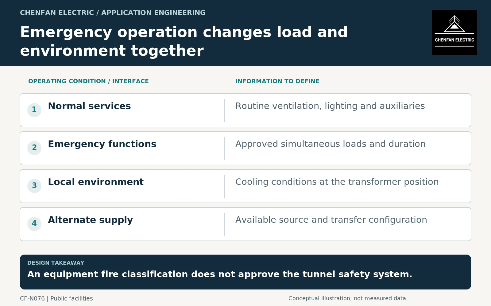
A tunnel distribution transformer should be evaluated for both normal services and the emergency states defined by the project’s safety design. Those states can change load combinations, source availability and local cooling conditions at the same time. Normal ventilation demand and a room-temperature assumption are not enough to establish the required emergency duty.
Use the approved emergency philosophy as an input
The tunnel’s responsible safety and electrical teams must identify which loads operate, which stop and what continuity is required in each event. This article does not determine statutory emergency loads, smoke-control operation or required service duration.
Translate the approved philosophy into transformer-side quantities: current, reactive demand, starting events and duration. Identify the transformer location and whether its cooling environment changes during the event.
General transformer application guidance supports rating and operating-condition review. It does not define the tunnel’s emergency strategy. [1]
Separate equipment classification from installation performance
Dry-type transformer requirements under IEC 60076-11 include relevant equipment environmental and fire-behavior classifications within their scope. They do not approve tunnel compartmentation, ventilation, smoke management or emergency-power continuity. [2]
The installation design must show how heat is removed in normal and required abnormal states. A transformer may be outside the tunnel bore yet depend on ventilation or services affected by the same event. Follow those dependencies rather than assuming a separate room is fully independent.
| Operating state | Required electrical and thermal inputs |
|---|---|
| Normal service | Coincident loads and local cooling conditions |
| Emergency ventilation | Approved fan combination, starts and duration |
| Alternate-source operation | Source strength and permitted load sequence |
| Partial equipment outage | Remaining supply and cooling capability |
| Restoration | Returning loads and initial thermal state |
Assess starting and sustained demand separately
Large ventilation motors can create a voltage-response case during starting, while continued operation creates a thermal case. The starting method and source configuration must be represented correctly.
Motor-acceleration study documentation supports analyzing the motor, starting device and source together. It is not evidence that every ventilation start can be accommodated by a generic transformer margin. [3]
For dry-type loading assessment, use the relevant loading guide and actual environmental assumptions. A temporary capability should not be extended to the entire required emergency duration without supporting analysis. [4]
Do not combine every theoretical maximum if the approved safety logic makes those loads mutually exclusive. Conversely, a noncoincidence assumption must be traceable to the implemented control philosophy and remain valid in the relevant failure state.
Freeze the coordinated boundary before procurement closes
The enquiry should reference the normal and emergency single-line diagrams, load schedules, source-transfer cases and local environmental conditions. The supplier should identify restrictions and the evidence covering the required transformer duty.
Acceptance should reconcile equipment ratings, room cooling, cable and switchgear capacity, and the implemented control sequence. A late change in emergency ventilation strategy can alter transformer duty even if normal energy consumption is unchanged.
The useful specification states which tunnel functions the transformer supports, under which source and environmental conditions, and for how long. It does not replace the tunnel safety design; it converts that design into a clear and testable equipment requirement.
Core procurement checkpoint: Freeze the tunnel assembly and cooling interfaces
A tunnel transformer core should be supplied to the equipment manufacturer’s approved geometry, including any assembly clearances affected by the chosen enclosure and cooling arrangement. The core’s dimensional envelope alone does not establish tunnel maintainability or emergency-loading capability. Define whether an assembled core or lamination set is required, and keep equipment cooling and emergency-system acceptance outside the core-only scope.
For the core enquiry: Approved core/window drawing; delivery form; clamp and handling interfaces; keep-clear requirements; equipment-level cooling and emergency acceptance owner.