

A water-treatment transformer should be assessed for the actual combinations of running and starting pumps. The number of motors or their summed kilowatts cannot establish acceptable voltage response or sustained duty. Lead-lag control, standby testing, process recovery and source strength can create different cases that need to be represented explicitly.
Convert the process sequence into electrical cases
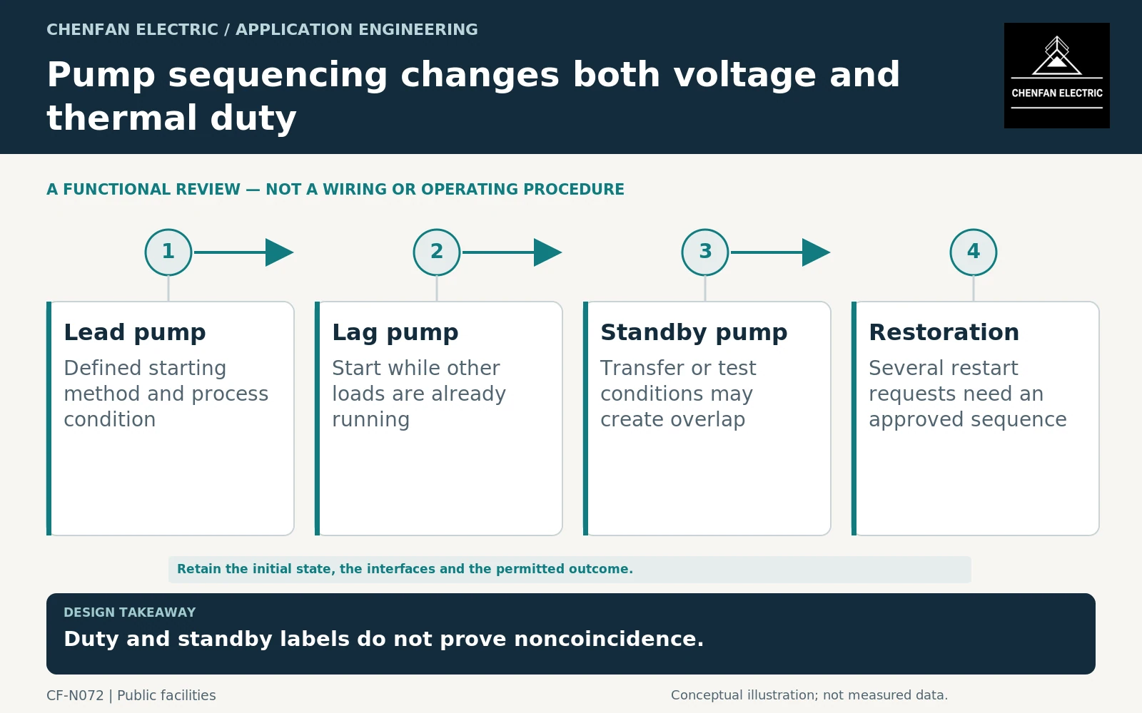
Obtain the pump operating philosophy: which pumps run normally, when additional pumps start, how standby equipment is tested and what happens after a supply interruption. A pump marked standby may overlap with the duty pump during transfer or testing unless the design prevents it.
For each motor, record the starting method and supplier data appropriate to the study. Direct-on-line, soft-start and drive-fed arrangements should not be assigned the same current model. Motor-acceleration tools explicitly address starting devices and sequence-of-events analysis. [1] [2]
The process condition matters too. Starting a pump against one hydraulic condition can differ from another. The electrical designer needs the approved motor and process inputs rather than a generic start multiplier.
Study the source and the sequence together
The transformer, cables, upstream source and running loads influence voltage during a new start. A transformer that can thermally tolerate the event does not automatically ensure that the motor accelerates or that other loads remain within their operating requirements.
General transformer application guidance addresses voltage variation, connections and ratings. It does not select the pump sequence without the process requirements. [3]
A useful case might be one lag pump starting while the lead pump and treatment auxiliaries operate. Another might be recovery after an outage with several start requests queued. These are conceptual cases; the actual sequence and acceptance criteria must come from the project.
Do not simply add every starting current simultaneously if controls make that state impossible. Equally, do not rely on noncoincidence unless it is enforced and remains true when the controller restarts or a manual operating mode is used.
Include sustained and repeated duty
Repeated starts and extended high-flow operation affect the chronological thermal duty. Record start frequency, recovery intervals and the load already present before each event. If a pump fails to accelerate, the resulting duty can differ from the intended successful start.
For variable-speed drives, request input current, reactive behavior and relevant spectra over the operating range. The motor’s mechanical output does not directly define the transformer’s converter-side input.
Mineral-oil loading guidance provides one equipment-specific thermal framework. It is not a universal permission to overload a transformer whenever the process requires another pump. [4]
Issue a process-linked acceptance matrix
The enquiry should contain the normal pump combination, credible starts, standby test conditions, restoration sequence and available source configurations. Identify any required load shedding or current restriction.
The supplier should confirm the transformer duty and provide parameters for the coordinated motor-starting study. The system designer should own the voltage-response and protection conclusions, while the process team confirms that the proposed sequence still delivers the required treatment service.
Acceptance should preserve that division of responsibility and verify the implemented sequence. Changing a standby policy or enabling simultaneous manual starts can invalidate the original study without changing a single motor nameplate.
The result is a transformer specification tied to how the water-treatment plant actually operates. That is more useful than a capacity allowance based on the sum of motor powers and an unexplained starting margin.
Core procurement checkpoint: Use the pump-starting assessment to release the core design
Multiple pump starts are reviewed using the transformer and network model, not the core drawing alone. After the manufacturer selects the equipment design, place the core order against its approved geometry and material requirements. Any request for excitation information should identify the test or model boundary; the core supplier should not imply that its manufacturing records demonstrate successful simultaneous starting.
For the core enquiry: Approved equipment design; core geometry; material specification; requested excitation records; responsibility for motor-starting and voltage-dip assessment.