

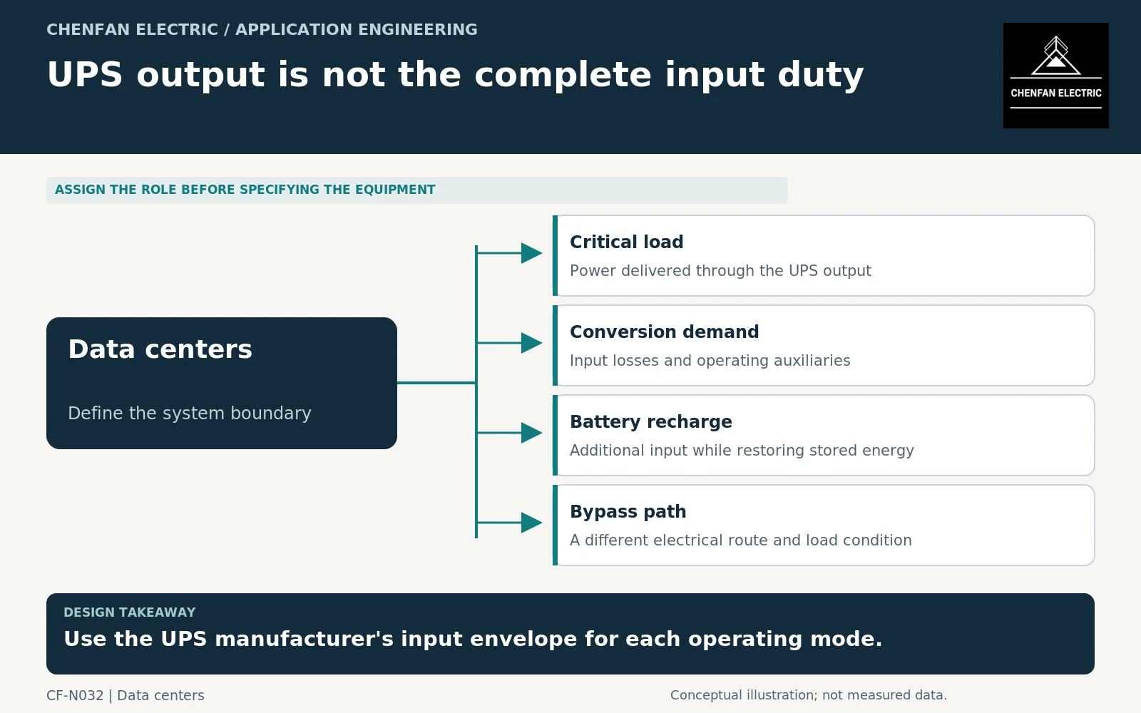
A transformer supplying an uninterruptible power system (UPS) should be evaluated from the UPS input envelope, including battery recharge where it can coincide with load supply. The critical-load output rating is not automatically the maximum alternating current (AC) input demand. Normal conversion, recharge, bypass and recovery after an outage can impose different current and waveform conditions.
Identify which path the transformer supplies
Draw the rectifier input, bypass input, battery connection and output load. Determine whether the same transformer supplies both rectifier and bypass paths or whether separate sources are used. A UPS system diagram is more informative than an isolated output-kilowatt figure.
IEC 62040-3 addresses UPS performance and test requirements within its scope. It is not a substitute for transformer rating or a guarantee that every upstream supply condition is acceptable. [1]
Request input current, power factor, efficiency information and permitted operating voltage for the actual UPS configuration. Keep measured, typical and guaranteed data distinct.
Add recharge at the correct boundary
After a battery-supported interval, the rectifier may supply the output load while restoring battery energy. The recharge setting and available input limit determine whether those demands coincide fully or whether one is restricted.
An illustrative accounting case with 1,000 kW of output load, 30 kW of conversion and auxiliary demand, and 150 kW of battery charging requires 1,180 kW at the assumed AC input boundary. Apparent power and current still require the actual input power factor and waveform. The numbers are assumptions for boundary arithmetic, not UPS performance claims.
Ask whether recharge is limited during generator operation or after a large facility restart. A setting that reduces demand on a weak source may differ from the normal utility-supplied setting.
Review bypass and recovery separately
| UPS mode | Transformer input to obtain |
|---|---|
| Normal conversion | Continuous input current at the stated output load |
| Recharge with load | Maximum permitted simultaneous input demand |
| Battery discharge | Remaining upstream loads and energized state |
| Static or maintenance bypass | Actual load path and current characteristics |
| Recovery after outage | Restart and recharge sequence with source limits |
The waveform seen in bypass can differ from the rectifier-input waveform because the load is connected through a different path. Do not use one brochure harmonic value for all modes without confirmation.
For nonsinusoidal transformer loading, the applicable assessment must respect the equipment scope. IEEE C57.110 is relevant to defined power and distribution transformer cases and excludes rectifier transformers; a dedicated converter-transformer arrangement may require a different specification basis. [2] [3]
Convert UPS settings into a durable specification
The transformer duty sheet should reference the UPS model, configuration and input-limit settings. Record the maximum recharge rate, permitted concurrency, bypass arrangement and generator-mode restrictions. These are design inputs, not optional operating notes.
General transformer application guidance supports matching the equipment to the stated loading and connection conditions. [4] Any thermal assessment should include the post-outage duration and initial state, not just the normal steady load.
Keep a change-control trigger for larger battery banks or revised recharge settings. More battery energy may lengthen recharge or encourage a higher recharge demand, even if the critical-load output remains unchanged. The transformer specification is complete only when it describes the actual upstream duty created by the UPS modes the facility intends to use.
Core procurement checkpoint: Identify the UPS transformer design before ordering laminations
A UPS input transformer core should be ordered against the actual rectifier-side design and approved winding envelope, including the conditions associated with battery recharge. Do not treat a UPS output-power label as a complete magnetic specification. Material or lamination inspection records can support traceability, but they do not replace the UPS manufacturer’s input-current information or the transformer manufacturer’s thermal assessment.
For the core enquiry: UPS design reference; core and window drawing; grade and thickness; joint sequence; associated operating-case revision.